element14 Community
element14 Community
    Register Log In
  • Site
  • Search
  • Log In Register
  • About Us
  • Community Hub
    Community Hub
    • What's New on element14
    • Feedback and Support
    • Benefits of Membership
    • Personal Blogs
    • Members Area
    • Achievement Levels
  • Learn
    Learn
    • Ask an Expert
    • eBooks
    • element14 presents
    • Learning Center
    • Tech Spotlight
    • STEM Academy
    • Webinars, Training and Events
    • Learning Groups
  • Technologies
    Technologies
    • 3D Printing
    • FPGA
    • Industrial Automation
    • Internet of Things
    • Power & Energy
    • Sensors
    • Technology Groups
  • Challenges & Projects
    Challenges & Projects
    • Design Challenges
    • element14 presents Projects
    • Project14
    • Arduino Projects
    • Raspberry Pi Projects
    • Project Groups
  • Products
    Products
    • Arduino
    • Avnet Boards Community
    • Dev Tools
    • Manufacturers
    • Multicomp Pro
    • Product Groups
    • Raspberry Pi
    • RoadTests & Reviews
  • Store
    Store
    • Visit Your Store
    • Choose another store...
      • Europe
      •  Austria (German)
      •  Belgium (Dutch, French)
      •  Bulgaria (Bulgarian)
      •  Czech Republic (Czech)
      •  Denmark (Danish)
      •  Estonia (Estonian)
      •  Finland (Finnish)
      •  France (French)
      •  Germany (German)
      •  Hungary (Hungarian)
      •  Ireland
      •  Israel
      •  Italy (Italian)
      •  Latvia (Latvian)
      •  
      •  Lithuania (Lithuanian)
      •  Netherlands (Dutch)
      •  Norway (Norwegian)
      •  Poland (Polish)
      •  Portugal (Portuguese)
      •  Romania (Romanian)
      •  Russia (Russian)
      •  Slovakia (Slovak)
      •  Slovenia (Slovenian)
      •  Spain (Spanish)
      •  Sweden (Swedish)
      •  Switzerland(German, French)
      •  Turkey (Turkish)
      •  United Kingdom
      • Asia Pacific
      •  Australia
      •  China
      •  Hong Kong
      •  India
      •  Korea (Korean)
      •  Malaysia
      •  New Zealand
      •  Philippines
      •  Singapore
      •  Taiwan
      •  Thailand (Thai)
      • Americas
      •  Brazil (Portuguese)
      •  Canada
      •  Mexico (Spanish)
      •  United States
      Can't find the country/region you're looking for? Visit our export site or find a local distributor.
  • Translate
  • Profile
  • Settings
Personal Blogs
  • Community Hub
  • More
Personal Blogs
John Wiltrout's Blog Exploring a TL494 PWM Control Circuit
  • Blog
  • Documents
  • Mentions
  • Sub-Groups
  • Tags
  • More
  • Cancel
  • New
  • Share
  • More
  • Cancel
Group Actions
  • Group RSS
  • More
  • Cancel
Engagement
  • Author Author: jw0752
  • Date Created: 30 Mar 2016 8:13 PM Date Created
  • Views 6215 views
  • Likes 3 likes
  • Comments 3 comments
  • tl494
  • ic_experiments
Related
Recommended

Exploring a TL494 PWM Control Circuit

jw0752
jw0752
30 Mar 2016

Once again I am playing with an IC I dug out of an old piece of equipment. Today it is the Texas Instrument TL 494 Pulse-Width-Modulation Control Circuit. The Data Sheet:


http://www.farnell.com/datasheets/1962656.pdf


which indicates that it was originally designed cerca 1983 but it remains relevant as Newark Electrons continues to supply it.


http://www.newark.com/texas-instruments/tl494cn/voltage-mode-pwm-controller-40v/dp/60K6995


The TL 494 has everything needed on chip to generate and control a PWM signal. This in turn can provide the ability to drive heavier current carriers such as transistors. The chip has two error amplifiers that can be used to control the output and an internal voltage reference and oscillator. The flexible output stage has 2 uncommitted transistors that can be hooked up as either common-emitter or emitter-follower configurations. The relatively low cost per unit from Farnell ($0.69) makes this a very desirable circuit for design of bench power supplies as it simplifies and integrates most of the circuitry needed.


The Data sheet has a sample circuit along with an excellent section by section description of the formulas and parameters for designing the circuit.  Here is a schematic of the sample circuit:


image


It is my indention in this exercise to breadboard this circuit and experiment with adjusting the output voltage and the current limiting circuit. As I proceed you will notice that I have strayed from using the exact components listed in the schematic. For example I might use a 47 K resistor where the schematic calls for a 51K or my inductor is a 100 uH instead of a 140 uH. These discrepancies will affect the final performance of the circuit. Other factors that will adversely affect the performance will be the resistance of the bread board contacts, long leads and jumpers, and the layout of the parts on the breadboard. While these things are all of concern their adverse effects are outweighed by the easy availability of the parts I will use and level of imprecision that I am willing to accept. This is an experiment and if there are serious problem then more will be learned as I search for a solution.


The above circuit, as designed, will supply 5 volts at 10 amps. I will begin with an attempt to get close to 5 volts with a limit of 2 amps. Since the contacts in the bread board and the gauge of the wires being used will not easily accommodate 10 amps. Here is a picture of the bread boarded circuit:


image


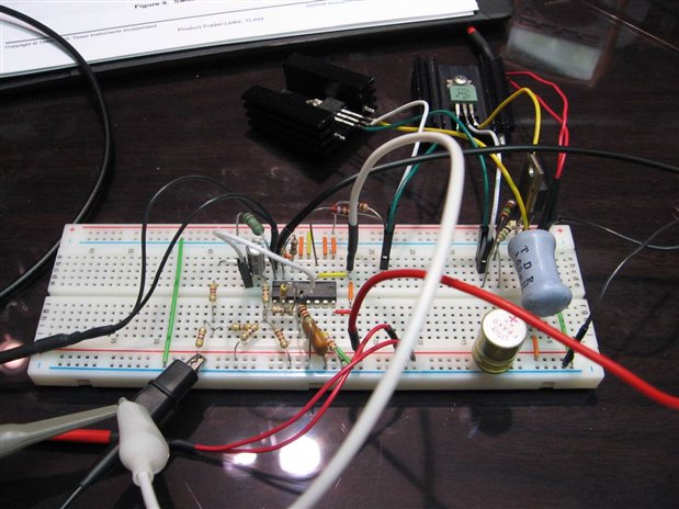
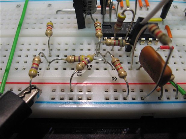
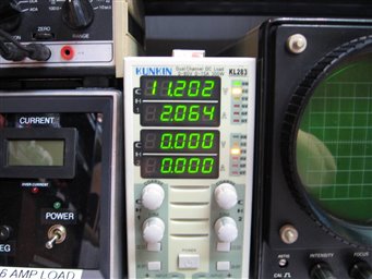
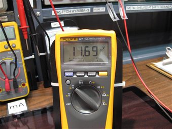
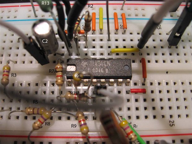
As you can see I have placed Q1 and Q2 on thier own heat sinks with jumper wires and bread board pins to tie into the circuit. I am using 4.7K resistors for R8 and R9 which are the output voltage sensing divider. As they have the same proportion to one another as the original 5.1 K we should not see any difference in the output voltage. The original design calls for R13 ( the current sense resistor) to be 0.1 Ohms. In my first test I will be using a 0.47 ohm resistor which should bring my current limitation down to about 2 amps. An electronic load will be used to test the circuit and I am monitoring the voltage output with the Fluke and the activity of the output of the TL 494 with the scope. The power supply will be set at approximately 27 volts for the input supply and I can also monitor the current draw on the supply with the meters of the power supply.


       imageimageimage


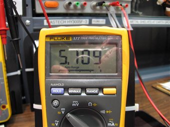
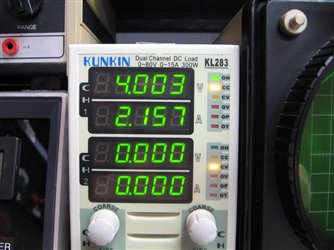
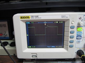
The load is reading 4 volts due to the voltage drop in the sense resistor and the wires and connections.  The scope illustrates the wave form of the output of the TL 494 on pin 11. The regulation of the power supply was well within expectations based on the inherent problems of connections and wire gauge being used in the circuit.


My next test involved changing the values of R8 and R9 to produce an output closer to 12 volts. Here is a photo where I have labeled R8 and R9.


image


The results:


        imageimageimage


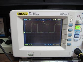
Here is what the scope looks like with no load on the circuit:


image


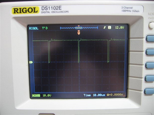
Now with R8 still at 4.7k and R9 at 1.2k the output of the circuit went to 12 volts as expected. Turning the load up the current increased until the voltage across the sense resistor R13 tripped the error amplifier in the TL 494 and the current dropped back to the limit imposed by the value of R13 compared to the voltage divider R1 and R2 supplied by the internal voltage reference. I also experimented powering resistive loads (auto brake lights). The duty cycle of the PWM on the scope would increase as the load was increased up until the current cut off and then then stabilize.


In case you want to look closer at my bread board here is another picture with some labels:


image


While the TL 494 is rather old I can see many uses for it in circuits that I may want to design in the future. It also provided a good evening of exploring and learning a little bit more about electronics.

  • Sign in to reply

Top Comments

  • clem57
    clem57 over 9 years ago +1
    I like your blog. Especially the large print for my old eyes. Clem PS How did you add the id's(R8, etc) to the picture? Very nice touch.
  • jw0752
    jw0752 over 9 years ago in reply to clem57 +1
    Hi Clem, Thanks the Large Print is intentional, I have to be able to see it to proof read it. John
  • DAB
    DAB over 9 years ago +1
    Great post John. Using PWM for managing power loads is an old standby technique still in use today. I suspect you will find this chip in may types of battery chargers or power supplies. Plus I too like…
  • DAB
    DAB over 9 years ago

    Great post John.


    Using PWM for managing power loads is an old standby technique still in use today.

    I suspect you will find this chip in may types of battery chargers or power supplies.


    Plus I too like the larger print. image


    DAB

    • Cancel
    • Vote Up +1 Vote Down
    • Sign in to reply
    • More
    • Cancel
  • jw0752
    jw0752 over 9 years ago in reply to clem57

    Hi Clem,

    Thanks the Large Print is intentional, I have to be able to see it to proof read it.

    John

    • Cancel
    • Vote Up +1 Vote Down
    • Sign in to reply
    • More
    • Cancel
  • clem57
    clem57 over 9 years ago

    I like your blog. Especially the large print for my old eyes.

    Clem

    PS How did you add the id's(R8, etc) to the picture? Very nice touch.

    • Cancel
    • Vote Up +1 Vote Down
    • Sign in to reply
    • More
    • Cancel
element14 Community

element14 is the first online community specifically for engineers. Connect with your peers and get expert answers to your questions.

  • Members
  • Learn
  • Technologies
  • Challenges & Projects
  • Products
  • Store
  • About Us
  • Feedback & Support
  • FAQs
  • Terms of Use
  • Privacy Policy
  • Legal and Copyright Notices
  • Sitemap
  • Cookies

An Avnet Company © 2025 Premier Farnell Limited. All Rights Reserved.

Premier Farnell Ltd, registered in England and Wales (no 00876412), registered office: Farnell House, Forge Lane, Leeds LS12 2NE.

ICP 备案号 10220084.

Follow element14

  • X
  • Facebook
  • linkedin
  • YouTube