element14 Community
element14 Community
    Register Log In
  • Site
  • Search
  • Log In Register
  • About Us
  • Community Hub
    Community Hub
    • What's New on element14
    • Feedback and Support
    • Benefits of Membership
    • Personal Blogs
    • Members Area
    • Achievement Levels
  • Learn
    Learn
    • Ask an Expert
    • eBooks
    • element14 presents
    • Learning Center
    • Tech Spotlight
    • STEM Academy
    • Webinars, Training and Events
    • Learning Groups
  • Technologies
    Technologies
    • 3D Printing
    • FPGA
    • Industrial Automation
    • Internet of Things
    • Power & Energy
    • Sensors
    • Technology Groups
  • Challenges & Projects
    Challenges & Projects
    • Design Challenges
    • element14 presents Projects
    • Project14
    • Arduino Projects
    • Raspberry Pi Projects
    • Project Groups
  • Products
    Products
    • Arduino
    • Avnet Boards Community
    • Dev Tools
    • Manufacturers
    • Multicomp Pro
    • Product Groups
    • Raspberry Pi
    • RoadTests & Reviews
  • Store
    Store
    • Visit Your Store
    • Choose another store...
      • Europe
      •  Austria (German)
      •  Belgium (Dutch, French)
      •  Bulgaria (Bulgarian)
      •  Czech Republic (Czech)
      •  Denmark (Danish)
      •  Estonia (Estonian)
      •  Finland (Finnish)
      •  France (French)
      •  Germany (German)
      •  Hungary (Hungarian)
      •  Ireland
      •  Israel
      •  Italy (Italian)
      •  Latvia (Latvian)
      •  
      •  Lithuania (Lithuanian)
      •  Netherlands (Dutch)
      •  Norway (Norwegian)
      •  Poland (Polish)
      •  Portugal (Portuguese)
      •  Romania (Romanian)
      •  Russia (Russian)
      •  Slovakia (Slovak)
      •  Slovenia (Slovenian)
      •  Spain (Spanish)
      •  Sweden (Swedish)
      •  Switzerland(German, French)
      •  Turkey (Turkish)
      •  United Kingdom
      • Asia Pacific
      •  Australia
      •  China
      •  Hong Kong
      •  India
      •  Korea (Korean)
      •  Malaysia
      •  New Zealand
      •  Philippines
      •  Singapore
      •  Taiwan
      •  Thailand (Thai)
      • Americas
      •  Brazil (Portuguese)
      •  Canada
      •  Mexico (Spanish)
      •  United States
      Can't find the country/region you're looking for? Visit our export site or find a local distributor.
  • Translate
  • Profile
  • Settings
Personal Blogs
  • Community Hub
  • More
Personal Blogs
John Wiltrout's Blog Exploring a Voltage Controlled Pulse Width Modulator Chip ( LTC6992)
  • Blog
  • Documents
  • Mentions
  • Sub-Groups
  • Tags
  • More
  • Cancel
  • New
  • Share
  • More
  • Cancel
Group Actions
  • Group RSS
  • More
  • Cancel
Engagement
  • Author Author: jw0752
  • Date Created: 19 Oct 2016 6:34 AM Date Created
  • Views 3795 views
  • Likes 7 likes
  • Comments 4 comments
  • ltc6992-3
  • voltage controlled pwm
Related
Recommended

Exploring a Voltage Controlled Pulse Width Modulator Chip ( LTC6992)

jw0752
jw0752
19 Oct 2016

Tonight I am experimenting with an LTC 6992 Voltage Controlled PWM IC. I had an application where I wanted to control a motor's speed using a variable voltage and the LTC6992 came up in my search. Here is the chip as listed on the Newark site:


http://www.newark.com/linear-technology/ltc6992cs6-1-trmpbf/timerblox-single-1mhz-5-5v-6-tsot/dp/24T2694


And here is the link to the Data Sheet from Linear Technology.


http://www.farnell.com/datasheets/1642034.pdf?_ga=1.70056336.1418853850.1451543312


My first challenge after receiving the chip from the vendor was putting it onto a workable board. I should be starting to get used to the size of these new surface mount ICs but they always seem to surprise me. The device that I received is a TSOT-23 package and way to small to deal with unless it is mounted on a board. I had some converter boards on the shelf but none of them were perfectly suited to this device. I finally ended up using an SOIC8 adapter board and although the legs didn't match the spacing on the board exactly I was able to solder bridge the difference. Here is the finished device now the size of a regular 8 pin DIP.


image


Now it doesn't take much to impress me but I found the features of the LTC6992 impressive and easy to use. The device comes in 4 variants designated by a -1, -2, -3, or -4 after the number. Page 17 of the data sheet explains that the differences between them have to do with the duty cycle ranges that they cover. The device I am testing is a LTC6992-3 which means that it will have a duty cycle range of 0% to 95% as the Modulation voltage varies from approximately 0.1 volt to 0.9 volt.


The device can run on a voltage supply of 2.25 Volts to 5.5 Volts. I ran my experiments at 5 volts. It is important to put a 0.1 uF decoupling capacitor between Pin 5 V+ and Pin 2 Ground for proper operation. Pin 1 is the Modulation and expects an input from 0.1 volt to 0.9 volt which will cause the chip to vary its PWM output from 0% to 95%. Voltages outside this range have no further effect but if the voltage is more than 0.3 volts above V+ or more that 0.3 volts below ground damage can result. For the purposes of this experiment I built a voltage divider with a 1K resistor and a 10K resistor and took my Mod input voltage across the 1K resistor. I did this since my power supplies are inaccurate and have poor resolution in the 0 to 1 volt range and the voltage divider allows me to use 0 to 10 volts on my power supply divided by approximately 10. I put a bench meter on the Mod pin and placed it near the Oscilloscope so that I could take simultaneous pictures to relate the voltage on the Mod Pin 1 to the Duty Cycle of the output on Pin 6.


This chip has two circuits that allow a designer to choose the frequency of the output. The first method uses a single resistor with a value between 50K and 800K connected between the #3 Set Pin and ground. A 50K resistor will generate an output of 1 MHz and the 800K will produce an output of 62.5 kHz. The second method uses the #4 Divide pin to introduce a divide by factor to further control the output. Internally the chip has a 4 bit ADC which takes the voltage on Pin 4 and converts it to a digital divider of the frequency. From 0 to 1/2 of V+ the ADC will move through 8 division ranges that will bring the output frequency to as low as 3.815 Hz. Once the voltage on Pin 4 is greater than 1/2 V+ the Polarity of the duty cycle reverses and 0 volts on the Mod Pin will produce 95% PWM and 0.9 volts on Pin 1 Mod will produce 0% PWM. This is very handy as it can serve as a negative feedback loop to stabilize a dynamic system.


My first experiments with the LTC6992 utilized an LED with a current limiting resistor on the #6 Output Pin. The device can supply or sink 20 mA but no more. Later in the experiment I will expand the output to an N Channel MOSFET and use it to drive a 24 volt motor.


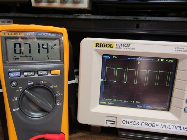
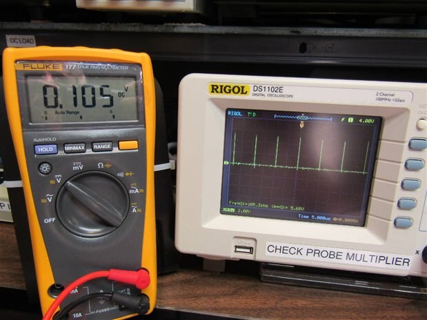
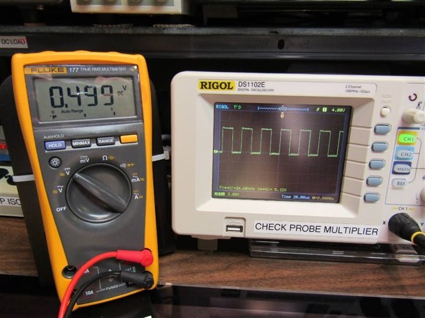
Here are pictures of the Mod voltage and the Oscilloscope output for voltages of 0.5 volts, 0.714 volts, and 0.105 volts. I am using a 470K resistor on the #3 Set pin which produces a frequency of 106.4 KHz on the output. The Data Sheet provides a simple formula for calculating the frequency. I found that the actual frequency very closely match the calculated frequency. For this part of the experiment I had the Divide Pin 4 tied to ground so that my divide by factor was 1. This also put the Mod to Output in a positive correspondence. PWM increases 0% to 95% as Pin 1 voltage increases 0.1 volt to 0.9 volt.


image


image


image


The next step in the experiment was to add a resistor divider to the Div Pin 4. I chose to use 1K from V+ to Pin 4 and 100 Ohm from Pin 4 to Ground. This choice should produce a divide by factor of 4. I calculated that this should produce an output frequency of 26.6 KHz. Here is a picture of the Oscilloscope and you can see that the frequency is indeed 26.6 KHz.


image


My next step was to switch the configuration of the resistors on Pin 4 so that the correspondence of the change of the input to the output would become negative. In this case as the Voltage on Pin 1 changes from 0.1 volt to 0.9 volt the output would change from 95% PWM to 0% PWM.


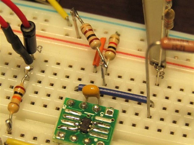
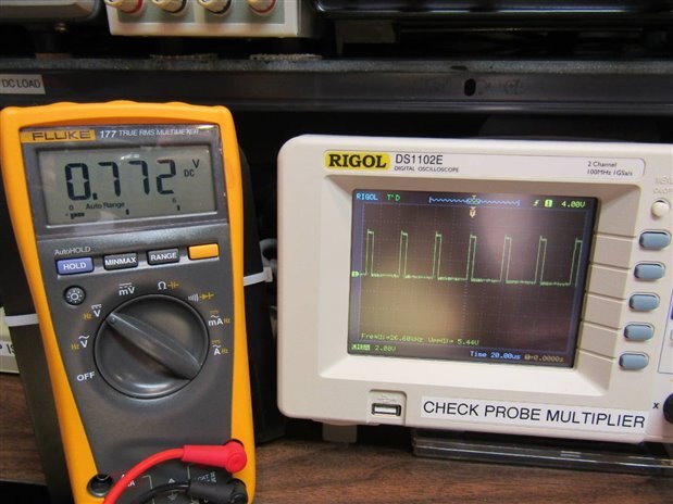
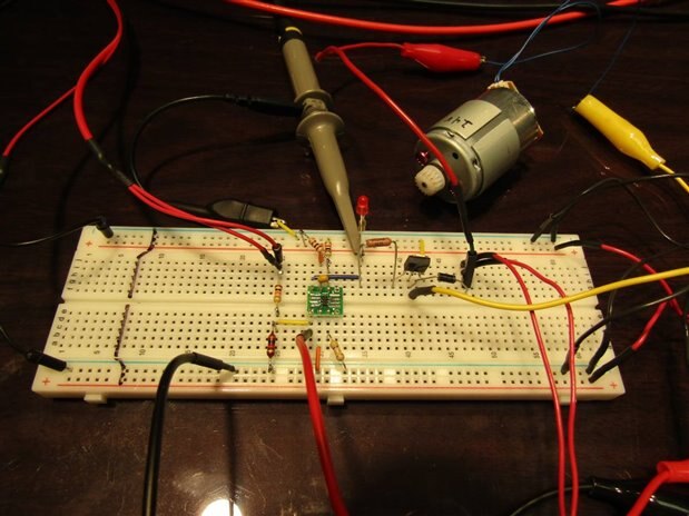
Here is a close up of the bread board at this point and a shot of the Oscilloscope showing the negative correspondence with the 0.772 volts corresponding to a very low % PWM.


image


image


The last part of my experiment was to add a 24 volt motor and a N CH MOSFET to drive it. Here is the breadboard set up.


image


I had a lot of fun tonight exploring the functionality of the LTC6992. I believe it will have some good applications in some of my projects in the future.


  • Sign in to reply

Top Comments

  • mcb1
    mcb1 over 8 years ago +2
    It's always good when the reality matches the theory and it all works the way you planned it ... first time. It seems the family now know what to buy you for xmas ... some SMD adaptor boards as the pesky…
  • DAB
    DAB over 8 years ago +1
    Good post John, You are making good progress in learning about and using electronic devices. Soon you will be making with the best of us. DAB
  • Piyushkamdi
    Piyushkamdi over 3 years ago

    Sir please mention the simple formula to calculate frequency in LTC6992

    • Cancel
    • Vote Up 0 Vote Down
    • Sign in to reply
    • More
    • Cancel
  • jw0752
    jw0752 over 8 years ago in reply to DAB

    Thanks DAB, I always appreciate your encouragement.

    John

    • Cancel
    • Vote Up 0 Vote Down
    • Sign in to reply
    • More
    • Cancel
  • DAB
    DAB over 8 years ago

    Good post John,


    You are making good progress in learning about and using electronic devices.


    Soon you will be making with the best of us.


    DAB

    • Cancel
    • Vote Up +1 Vote Down
    • Sign in to reply
    • More
    • Cancel
  • mcb1
    mcb1 over 8 years ago

    It's always good when the reality matches the theory and it all works the way you planned it ... first time.


    It seems the family now know what to buy you for xmas ... some SMD adaptor boards as the pesky little critters ain't going away.


    Mark

    • Cancel
    • Vote Up +2 Vote Down
    • Sign in to reply
    • More
    • Cancel
element14 Community

element14 is the first online community specifically for engineers. Connect with your peers and get expert answers to your questions.

  • Members
  • Learn
  • Technologies
  • Challenges & Projects
  • Products
  • Store
  • About Us
  • Feedback & Support
  • FAQs
  • Terms of Use
  • Privacy Policy
  • Legal and Copyright Notices
  • Sitemap
  • Cookies

An Avnet Company © 2025 Premier Farnell Limited. All Rights Reserved.

Premier Farnell Ltd, registered in England and Wales (no 00876412), registered office: Farnell House, Forge Lane, Leeds LS12 2NE.

ICP 备案号 10220084.

Follow element14

  • X
  • Facebook
  • linkedin
  • YouTube