


In the good old days (I remember them well) we didn't use any of the newfangled highfalutin semi conductors to regulate current. When necessary for short term precision current regulation we used a mechanical current regulator like this one:

It is built a little like a high quality buzzer and you can see the precision adjustments for both the tension on the armature and for the position of the contact points. As the current in the coil increases the contact is opened for a longer period of time. In this way, much like a PWM circuit the current is averaged over the amount of time on and the time off. This current regulator circuit was used to drive the heater filament in an x-ray tube. The mass of the filament allowed it to average the energy from the on and off pulses delivered by the regulator.
Incidentally the energy of an x-ray beam produced by an x-ray tube is controlled by the voltage potential between its anode and cathode. The current that is delivered to the filament controls its temperature and therefore the supply of free electrons that are available to be accelerated into the tungsten target. The more electrons that are available the greater the density or brightness of the x-ray radiation. This current regulator was in essence a brightness control for the x-ray beam. Most x-ray machines are rated based on their kVp and their mA. Modern chair side dental x-ray machines are usually in the range of 70 kVp and 5 mA. Back in the days of this mechanical regulator 90 kVp and 15 mA were more common as the sensitivity of the film wasn't as good and of course there were no digital electronic sensors. The other control that is available for exposing the film or sensor is the amount of time that the beam is applied. As you can imagine the x-rays were applied for a much longer time years ago than they are now. When Grandpa had his x-rays taken back in the 1950s he got several hundred times as much radiation as you do now when you visit the dentist for the same pictures.
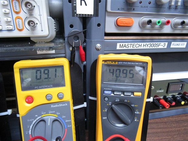
For the fun of it I hooked this old regulator up to an LED and started to turn up the voltage. At 20 volts the circuit began to regulate at around 15 mA and between 30 and 60 volts the regulation of the mA had about a 10% tolerance around 10 ma.
Here are some pictures from my experiment:
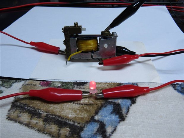
Since the regulator is at its core a small buzzer and it produces a low pitched tone that increases in frequency as the voltage is turned up.
John
Top Comments