


There are three circumstances that have come together to inspire me to assemble this little test adapter circuit. First of all I like to and I am continually salvaging components from circuit boards. As many of these circuit boards come from equipment used in dental clinics there are a lot of components related to control of motors, solenoids, and other real world mechanical interfaces. I salvage a fair number of MOSFETs and as they are occasionally OEM or unmarked I have to always cobble a test circuit together to make sure they work and to find the gate voltages.
The second circumstance was that my Element 14 friend Shabaz, in a reply to another member, called my attention to a Web Site called "Talking Electronics" and specifically to a book with 50 555 circuits. http://www.talkingelectronics.com/projects/50%20-%20555%20Circuits/50%20-%20555%20Circuits.html . After looking through the book I noticed a simple 555 PWM circuit that would fit perfectly into what I envisioned for a permanently assembled MOSFET and Zenner tester.
The final piece to my puzzle was that after 45 years I have finally broken down and replaced my old analog scope with a 2 channel digital scope by Rigol. Here again I have to thank my E-14 friends for all their counsel in helping me decide which scope was right for me. There have been several really nice presentations lately by some of our leading engineers about scopes and how to use them.
I call my circuit a "test adapter" not a "tester" as it is not self sufficient. It requires two power sources and a two channel oscilloscope to make it work and to read the output. The first variable power supply powers the 555 PWM circuit which in turn is used to drive the gate of the MOSFET that is under test. The second variable power supply provides Vdd for the MOSFET and also a test level voltage if a Zenner is being tested. The Oscilloscope attaches to test points on the adapter circuit and monitors the voltage level of the PWM signal to the gate of the MOSFET with one channel and the inverted output of the MOSFET with the second channel. Here is the schematic of the Test Adapter Circuit.

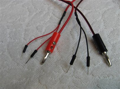
As you can see this is not a complicated project. One of the first things that you may notice however is that I have four ground header pins and two header pins for each of the power supplies V+ inputs. This is a result of the way I make up my power supply cords. For convenience when bread boarding I terminate my cords with a "Y" adapter to two 22 ga. pins. I find this is very convenient for making better contact with the bread board and also allows me to power the rails on both side of the bread board without using extra jumpers. Here is a picture of my power supply cords.
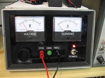
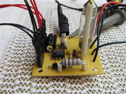
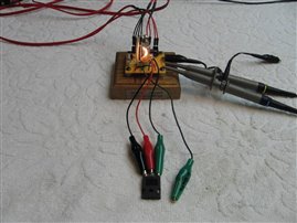
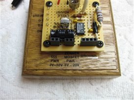
The PWM part of the adapter is powered by a supply (pictured above) that can go as high as 30VDC. On the schematic, I have marked the voltage input as 3VDC to 12VDC. Having had many bad experiences in the past, I did not trust myself not to accidently turn the supply above the 18VDC kill level for the NE555 timer IC. Therefore the circuit incorporates a 100 ohm resistor and a 15 volt Zenner diode to limit the Vcc to the 555. The minimum voltage of 3VDC is required because the NE555 will not operate in a stable configuration with less than this level. When I first bread boarded and tested the circuit this caused me some problems as the 3 volts is too high to get a measurement of Threshold, Linear, and Saturation for the MOSFETS with logic level gates. To cover this problem a voltage divider was added to the output of the PWM circuit so that gate test voltages could be brought down under a volt. To accommodate these two PWM output levels the tester has a wire with an alligator clip for a high level gate, (3 volts to 12 volts) and a wire with an alligator clip for the low level gates ( less than one volt to 4 volts) In the picture you can see the extra low level gate wire which is not being used in this Test.
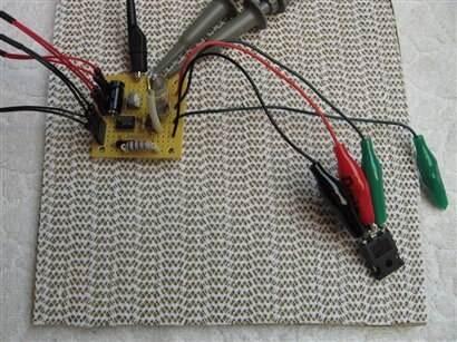
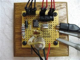
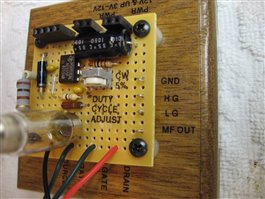
The oscilloscope channel one test probe has to attach to the proper test point on the board and follow the choice of high or low gate output clip so that it can properly monitor the signal and voltage level being delivered to the gate. There are test points provided on the board for each of these gate clips. See the picture above. After the final assembly these test points will be labeled but for now they are left to right ( MOSFET output, Low Gate output, High Gate output, Ground).
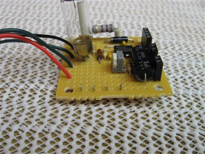
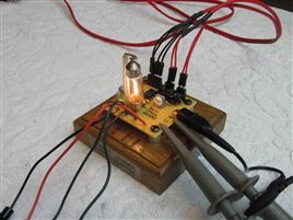
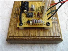
VR-1 allows one to vary the duty cycle of the MOSFET under test from 5% to 95%. While this is fluff, it is fun to turn the trimmer and watch the load bulb brighten and dim. Turning the trimmer fully counter clockwise gives full 95% duty cycle. Here are a couple of pictures of the circuit under test where the components described so far can be seen. You can see the purpose for the four female ground headers and two each female + power headers in the picture.
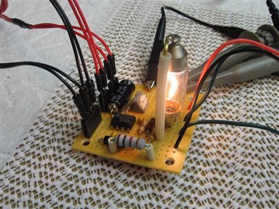
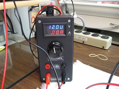
The second power supply (pictured below) is used to provide a Vdd voltage to the MOSFET. In series with this voltage supply I have a 12 volt automotive bulb that draws approximately 500 mA at full brightness. It is the light in the picture above. The test point for the channel two oscilloscope probe is attached to the circuit at the junction between this load bulb and the drain of the MOSFET. This has the effect of giving us an inverted output on the scope. When the PWM signal from the NE555 goes high it turns on the MOSFET which pulls the channel two probe and the load low.
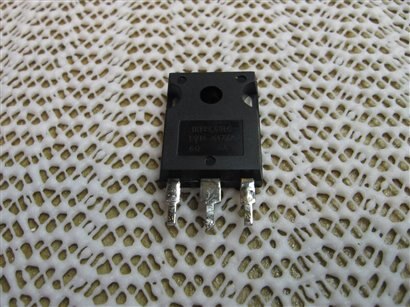
For the purpose of this demonstration I have used an IRFPC601C MOSFET. The Vdd supply to the MOSFET is 12 volts.
The first power supply, that provides Vcc for the PWM part of the circuit, will be varied from a value below the Threshold of the MOSFET to the Threshold, into the Linear Region and finally to the point of Saturation. The voltage will be monitored and displayed on the scope and we can watch the effect on the output which is displayed on scope channel 2. As we raise the voltage and note the effect on the output we can record the key voltage points for this specific MOSFET. Here are some screen shots from the oscilloscope for each of these points.

As you can see for a gate voltage of 4 volts we are just beginning to see a response from the MOSFET. Since the MOSFET is basically turned off at this point the channel 2 is still at 13.4 volts in this case. Note that I have the voltage monitor for channel 2 set at Vmax. This was a mistake as it would have been much more meaningful if it had been Vp-p. Channel one is set to be monitored properly at Vmax.

Here the voltage to the gate of the MOSFET is at 4.4 volts and you can see that we are now into the Linear region as we are seeing an inverted response on channel 2 of the scope. The Vmax for channel 2 is still over 12 volts but we can at least estimate that the peak to peak is 7 volts from the height of the waveform.

Finally, with 4.8 volts on the gate we are in full Saturation and the application of any more gate voltage has little to no effect. The output voltage peak to peak of channel 2 now looks to be 12 volts. We now have a good visual of how the output has changed as we moved the gate voltage from 4 volts to 4.8 volts.
As I was finishing bread boarding and testing the circuit I realized that it would provide an easy platform for testing a Zenner Diode too. This is simply accomplished by connecting the diode cathode to the Drain Clip and the diode anode to the Source Clip. The MOSFET power supply is then slowly increased from zero volts and the oscilloscope channel two is watched for the point where the voltage plateaus due to the breakdown of the zenner junction. Current through the zenner is limited by the 12 volt load bulb but it is still important not to turn the voltage unnecessarily high.
How can this circuit be of use if you do not have an oscilloscope? While not quite as nice and graphic, multimeters can be substituted for the oscilloscope channels. The PWM circuit should be turned to full duty cycle so that the voltage that is being read by the meters closely approximates the peak voltage and not the average voltage. If you do not turn the duty cycle all the way up your gate readings will be low by some percentage of reality. If I were making this adapter specifically for multimeters I would probably eliminate the PWM generator and use buffered DC voltage directly from the power supply to give me the most accurate readings for Threshold, Linear, and Saturation points. Though this would have perhaps been simpler, it would not have allowed me to make the MOSFET work and make pretty lines on my Oscilloscope.
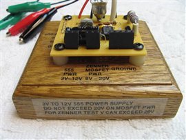
Here is the completed MOSFET Zenner Diode Test Adapter, mounted and labeled for use. I had to save these pictures for last as I have been producing this blog while waiting for the base to be finished by my friend Mike who is a cabinet maker.
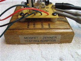
Thanks John
Top Comments
-

D_Hersey
-
Cancel
-
Vote Up
0
Vote Down
-
-
Sign in to reply
-
More
-
Cancel
-

jw0752
in reply to D_Hersey
-
Cancel
-
Vote Up
0
Vote Down
-
-
Sign in to reply
-
More
-
Cancel
Comment-

jw0752
in reply to D_Hersey
-
Cancel
-
Vote Up
0
Vote Down
-
-
Sign in to reply
-
More
-
Cancel
Children