


One of my sons Mario, who works repairing automated machines for a local manufacturer, was talking about the 3 phase power that they use. I told him about the interesting 3 phase generator that shabaz built and tested the other day and that I wanted to learn more. He suggested that I take a look at a small single phase 220 volt to 3 phase 220 volt Variable Frequency Drive (VFD) that he had.
NOTE of CAUTION! This experiment involves lethal voltages and should not be attempted without proper tools and experience.
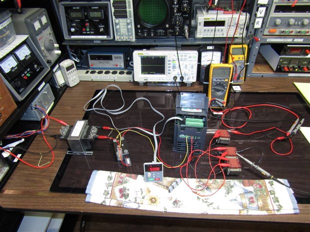
Here is the experiment that I set up to check out the drive also called an inverter. Out of sight to the left is an isolated variac AC supply that I can dial from 0 VAC to 150VAC. To get the 220 volts specified by the VFD I am using the step up transformer with the white sticker. I am using 2 fused lines to bring the 220 volts single phase power from the transformer to the VFD. On the output of the VFD I have placed one small 220 volt transformer across each phase. Since this unit is designed to power a 3 phase motor I wanted to put a similar load on each phase. I don't know if this is important or not but I didn't want to take a chance with a piece of equipment that didn't belong to me.
At this point I turned on the power and tried to get the VFD to function. While it lit up the control panel and I could see LEDs inside the unit there did not seem to be any combination of keys that I could push that made any voltage appear at the output. Going on the assumption that the problem was not with the VFD but more likely with the ignorant operator I turned things off and went to the internet for information. It did not take me long to realize that this cheap little VFD was a lot more complicated than I thought. I had found a 210 page instruction manual which was unfortunately written for people like my son with a lot more automation experience than I had.
Roughly 2 and a half hours later I was starting to make progress. While the book talked about programming the unit, I figured out that what they really meant was that the unit had to be configured to do what one wanted. To begin with I had to enter a code to tell the unit to accept commands from the little control panel in the foreground. I had to choose start mode and a couple other options each requiring a code be entered. Finally with the right code I was able to assign control of the frequency to the small potentiometer on the control panel.
Now when I pushed RUN the unit would power up and start the fan. I was able to measure 230 VAC across each phase of the three phase output labeled "U", "V", and "W" when the max 50 Hz was selected. This would drop to 0 VAC as the frequency was turned down to zero.

I hooked my scope up to the secondary of one of the small transformer that was putting out 0 VAC to 13 VAC rms depending on where I had the frequency set. As the frequency knob was turned the display would look the same only more or less compressed in time. While you can see a reading of 69 Hz on my scope this was an anomaly captured by the camera. The frequency was jumping around due to my scopes difficulty in reading this wave form but I could see that the general reading followed the frequency displayed on the control panel.

Here is a closeup of the three transformers across the phases as well as the secondaries where I have the scope and voltmeter attached.
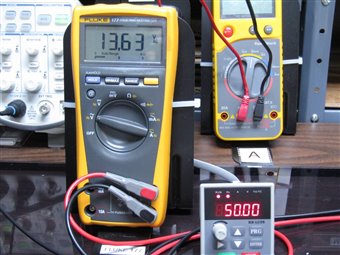
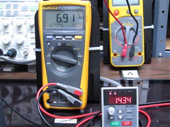
Here you can see the effect on the rms voltage of moving the frequency from 50 Hz to 14.34 Hz.
Tomorrow I am going to go to the local motor repair shop and see if I can rent a small, under 1/3 HP, 3 phase motor and experiment with it. I will post a follow up tomorrow night.
NOTE of CAUTION! This experiment involves lethal voltages and should not be attempted without proper tools and experience.
John
Top Comments