element14 Community
element14 Community
    Register Log In
  • Site
  • Search
  • Log In Register
  • Community Hub
    Community Hub
    • What's New on element14
    • Feedback and Support
    • Benefits of Membership
    • Personal Blogs
    • Members Area
    • Achievement Levels
  • Learn
    Learn
    • Ask an Expert
    • eBooks
    • element14 presents
    • Learning Center
    • Tech Spotlight
    • STEM Academy
    • Webinars, Training and Events
    • Learning Groups
  • Technologies
    Technologies
    • 3D Printing
    • FPGA
    • Industrial Automation
    • Internet of Things
    • Power & Energy
    • Sensors
    • Technology Groups
  • Challenges & Projects
    Challenges & Projects
    • Design Challenges
    • element14 presents Projects
    • Project14
    • Arduino Projects
    • Raspberry Pi Projects
    • Project Groups
  • Products
    Products
    • Arduino
    • Avnet & Tria Boards Community
    • Dev Tools
    • Manufacturers
    • Multicomp Pro
    • Product Groups
    • Raspberry Pi
    • RoadTests & Reviews
  • About Us
  • Store
    Store
    • Visit Your Store
    • Choose another store...
      • Europe
      •  Austria (German)
      •  Belgium (Dutch, French)
      •  Bulgaria (Bulgarian)
      •  Czech Republic (Czech)
      •  Denmark (Danish)
      •  Estonia (Estonian)
      •  Finland (Finnish)
      •  France (French)
      •  Germany (German)
      •  Hungary (Hungarian)
      •  Ireland
      •  Israel
      •  Italy (Italian)
      •  Latvia (Latvian)
      •  
      •  Lithuania (Lithuanian)
      •  Netherlands (Dutch)
      •  Norway (Norwegian)
      •  Poland (Polish)
      •  Portugal (Portuguese)
      •  Romania (Romanian)
      •  Russia (Russian)
      •  Slovakia (Slovak)
      •  Slovenia (Slovenian)
      •  Spain (Spanish)
      •  Sweden (Swedish)
      •  Switzerland(German, French)
      •  Turkey (Turkish)
      •  United Kingdom
      • Asia Pacific
      •  Australia
      •  China
      •  Hong Kong
      •  India
      • Japan
      •  Korea (Korean)
      •  Malaysia
      •  New Zealand
      •  Philippines
      •  Singapore
      •  Taiwan
      •  Thailand (Thai)
      • Vietnam
      • Americas
      •  Brazil (Portuguese)
      •  Canada
      •  Mexico (Spanish)
      •  United States
      Can't find the country/region you're looking for? Visit our export site or find a local distributor.
  • Translate
  • Profile
  • Settings
Personal Blogs
  • Community Hub
  • More
Personal Blogs
John Wiltrout's Blog Process Duration Timer Part 2 (Power Supply)
  • Blog
  • Documents
  • Mentions
  • Sub-Groups
  • Tags
  • More
  • Cancel
  • New
  • Share
  • More
  • Cancel
Group Actions
  • Group RSS
  • More
  • Cancel
Engagement
  • Author Author: jw0752
  • Date Created: 28 Jul 2017 6:22 AM Date Created
  • Views 2226 views
  • Likes 8 likes
  • Comments 3 comments
  • diytestequipch
  • power supply
Related
Recommended

Process Duration Timer Part 2 (Power Supply)

jw0752
jw0752
28 Jul 2017

Before I show you the power supply module for this project I thought I would share the basic block diagram of the different modules and how the power and control lines will interconnect.


image


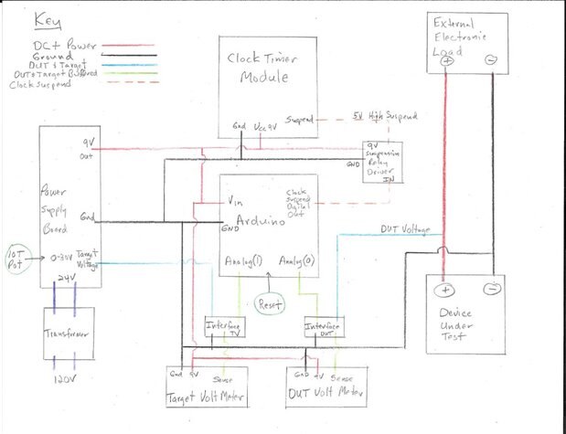
As any of the experienced builders on e14 will tell you the more planning that you do ahead of time the less rebuilding you will have to do down the line. I always like to know generally where I am going with a project. This doesn't keep me from changing my mind or having to readjust my plans due to unavailability of parts or if my imagination gets ahead of the technology I can afford. The general block diagram for the hardware and the Flow Chart for the software are useful tools to keep me focused and on track to the goal of a completed functional device.


The main topic of this blog is the Power Supply Module for the Process Duration Tester. As I have done in several of my recent projects I am going to use an inexpensive Chinese linear power supply kit and then modify it to suit my needs. Before I show you what the module looks like here are my perceived power needs for this project:


1. General 9 volt 1 Amp output to power the Arduino Vin, The two voltmeters, The Clock Module, and with an additional buck to 5 volts to drive the suspension relay of the clock module.

2. 0 to 30 volt variable output to serve as the Target Voltage for the termination of the timing sequence.


The need for the 5 volt drop off the 9 volt line comes as a correction to a mistake that I made in my planning and modification of the clock module. I had originally hoped that the digital output of the Arduino could drive the suspend relay on the clock module. When I got around to actually taking preliminary readings on the actual current draw of the relay I discovered that the 100 mA draw would mean that a driver circuit would be needed between the arduino and the clock suspend relay. The voltage needs to be 5 volts as this is the continuous duty cycle rating of the relay. In order to conserve the power load on the 9 volt DC/DC converter module I will probably just use another 5 volt DC/DC converter down line. Those of you who have seen some of my other projects know that I love the little Recom R78 series of DC to DC converters. Here is a listing for one from Newark.


http://www.newark.com/recom-power/r-78e5-0-0-5/dc-dc-converter-2-5w-5v-0-5a-sip/dp/62X9499?ost=R-78E5.0-0.5&scope=partnumberlookahead&exaMfpn=true&searchref=searchlookahead&searchView=table&iscrfnonsku=false&ddkey=http%3Aen-US%2FElement14_US%2Fw%2Fsearch


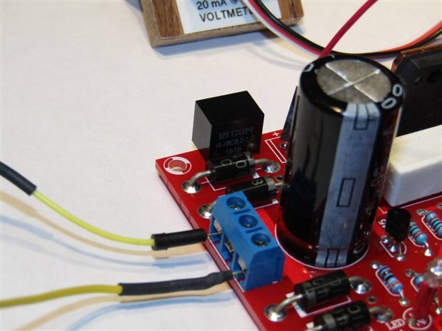
The 9 volt unit I am using is a Recom R78C9.0 -1.0 and can deliver 9 watts of power when supplied by a 10 to 42 volts input. If you look closely in one of the following pictures you will see the R78C9.0 as it usually fits nicelly into the footprint of a standard 78XX series linear regulator. I will probably use an R78E5.0-0.5 to convert the 9 volt supply to a 5 volt source to drive the relay.


Here is a picture of the power supply board with some notes around the edge:


image


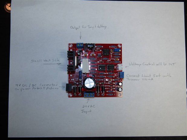
The nice thing about these boards is that they are a kit so I have the fun of building them before I use or modify them. The construction of this kit did not go without a glitch however. I am not sure if it is the late hours that I usually work or just the senior moments that seem to be happening more frequently but I got two wires to the voltage control pot, which is remote from the board itself, switched. This over sight tied the output of one of the regulation Op Amps to the control wiper and besides not working correctly caused the Op Amp to heat up under the output short to ground it was suffering when the control was turned all the way down. Fortunately the TL081 is a tough little Op Amp and I caught the problem before I fried anything.


I made a few modifications to the power supply board to suit my needs. As I mentioned I installed the 9 volt DC to DC converter in place of the linear regulator that is usually used to drive a cooling fan for the main power output transistor. Here is a closeup of the converter:


image


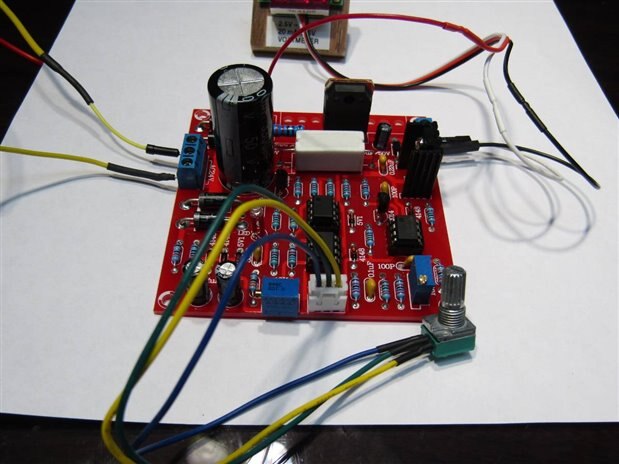
When properly supported this board can put out 30 volts at 3 amps. I am going to use it for a target voltage source which will have to power a 150 uA voltage sense line on a cheap Chinese meter and also power the voltage divider which will make its modified output palatable to the Arduino's 5 volt analog inputs. This means that I am lifting a feather with a truck jack. Aesthetically this bothers me a little but it will work and I really can't provide the 9 volt source and a 0 to 30 volt variable source in any better (translate cheaper) way. Another advantage to using this board is that it will afford some degree of regulation so that the target voltage does a minimal amount of wandering around.


I have replaced the normal current limiting pot on the board with a small trimmer and set it so that it will limit output to 500 mA. I have left the main heat sink off the output transistor to save space as the low current it will be handling can easily be handled by the device itself.


I will be installing a 10 turn pot on the voltage control so that it is easier to choose an accurate target voltage. When I took these pictures I was still testing with the standard 10K pot that comes with the kit.


image


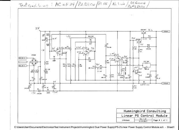
As an additional aid to anyone who wants to use this same board for some of their own projects I offer this re-drawn schematic on which I have penciled some voltage readings. Since my senior moments often cause things to not work as planned I took the time to analyse the board and record normal operational voltages for use in troubleshooting. Sorry if the hand written voltages are hard to see.


image


In case you are looking for the source on this board I get mine from here:


https://www.banggood.com/0-30V-2mA-3A-Adjustable-DC-Regulated-Power-Supply-DIY-Kit-p-958308.html?rmmds=myorder


I will be back in a few days with some more attempts at progress.


John


https://www.element14.com/community/people/jw0752/blog/2017/08/03/process-duration-timer-part-3-interfaces

  • Sign in to reply

Top Comments

  • mcb1
    mcb1 over 8 years ago +2
    and with an additional buck to 5 volts to drive the suspension relay of the clock module. John are you meaning the 5v is required for the relay coil.?? If I recall most (not all) 5v regulators on Arduino…
  • jw0752
    jw0752 over 8 years ago in reply to DAB +1
    Hi DAB, Thanks, I have no doubt that you are right about the practicality of the 10 turn pot. And you are right the precision that I will gain in setting the target is not likely to make any difference…
  • jw0752
    jw0752 over 8 years ago in reply to DAB

    Hi DAB,


    Thanks, I have no doubt that you are right about the practicality of the 10 turn pot. And you are right the precision that I will gain in setting the target is not likely to make any difference in the net precision of the device. What I need is for you to design an intelligent potentiometer for me that will change fast if I turn it fast and drop to precision level when I turn it slow, kind of like my computer mouse. Thanks again as I always enjoy your insights.


    John

    • Cancel
    • Vote Up +1 Vote Down
    • Sign in to reply
    • More
    • Cancel
  • DAB
    DAB over 8 years ago

    Nice update John.


    The power supply board looks well made.


    I suspect that you will find the 10 turn POT tedious to adjust.


    Unless you are looking for millivolt precision, I would go with a standard POT.


    It will be faster to adjust and you probably will not need better precision.


    DAB

    • Cancel
    • Vote Up 0 Vote Down
    • Sign in to reply
    • More
    • Cancel
  • mcb1
    mcb1 over 8 years ago
    and with an additional buck to 5 volts to drive the suspension relay of the clock module.

    John are you meaning the 5v is required for the relay coil.??


    If I recall most (not all) 5v regulators on Arduino boards can deliver 150mA, which may save you needing a 9-5v regulator.


    Mark

    • Cancel
    • Vote Up +2 Vote Down
    • Sign in to reply
    • More
    • Cancel
element14 Community

element14 is the first online community specifically for engineers. Connect with your peers and get expert answers to your questions.

  • Members
  • Learn
  • Technologies
  • Challenges & Projects
  • Products
  • Store
  • About Us
  • Feedback & Support
  • FAQs
  • Terms of Use
  • Privacy Policy
  • Legal and Copyright Notices
  • Sitemap
  • Cookies

An Avnet Company © 2025 Premier Farnell Limited. All Rights Reserved.

Premier Farnell Ltd, registered in England and Wales (no 00876412), registered office: Farnell House, Forge Lane, Leeds LS12 2NE.

ICP 备案号 10220084.

Follow element14

  • X
  • Facebook
  • linkedin
  • YouTube