


I will begin this blog by showing you how I have mounted the power supply into the project box that will be used for the Process Duration Timer. After a lot of searching in my transformer grave yard I found one that will allow the power supply to deliver 0 to 30 volts for the Target Clock Off Voltage. I have mounted a Recon R78C9.0-1 DC to DC converter to the power supply board. This will supply Vin to the Arduino as well as power the clock and the voltmeters for the Test Voltage and Target Voltage. Here are a couple pictures of the power supply and transformer mounted in the project box:
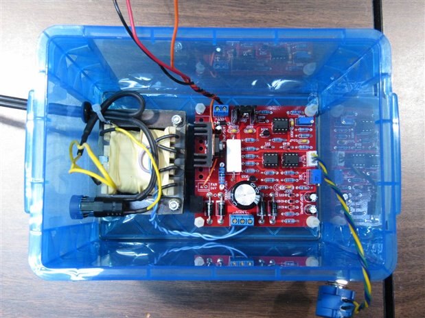
The loop of yellow wire will run to the main power switch. I have not yet planned the layout of the instrument and control panel. The Yellow , Blue, and Green twisted line in the lower right goes to the potentiometer that controls the Target Voltage which is supplied by the black common and red wire that exit to the top of the picture. The orange wire is the 9 volt supply.


I have fused the primary with a 500 mA Slow Blow fuse and mounted the power cord with a strain relief. The power cord is extreme over kill on gauge as it came off an Iron but it was more flexible than the lesser gauge cords in the box.
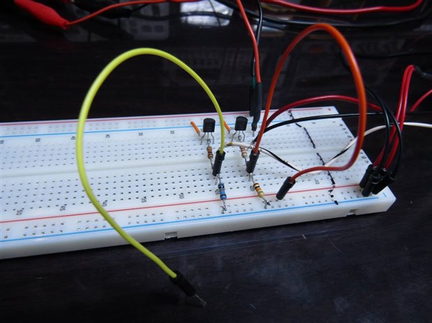
Since my last blog on this project I have been working on the interface between the Arduino and the Clock board. I wanted the Arduino to be able to send a High out one port to enable power to the Clock board and also send a High out a second port to put the clock into Suspended Animation. The plan is to have the Arduino turn off the clock once on reset (I will call it START eventually) and then keep the clock powered until the Reset is pushed again. Once the Reset is pushed and the clock is timing the Arduino will busy itself comparing the Test Voltage to the Target Voltage. As soon as the Process that is lowering the Test voltage brings it below the Target Voltage the Arduino will send the High out the second port and suspend the Clock. At this point the Arduino will pause until I come back at a later time to record the elapsed time on the clock and reset the experiment. There is minimal challenge to this interface as it is a very standard circuit for this purpose. I am using (2) 2N7000 N Channel Mosfets to do the heavy lifting. Here is the circuit that I put together and tested.
And Here is a Schematic:

For those of you with sharp eyes the bread board doesn't match the schematic. The schematic is the correct configuration, though the bread board works this way it isn't the right way to do it.
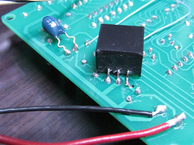
One thing of interest since last time is that I have solved the problem of where I was going to get the 5 volts to energize the relay that puts the clock into suspended animation. I remembered that while the clock itself has a Vin of 9 volts it was followed in the circuit by a 78L05 voltage regulator. This is a small TO-92 device and I didn't trust it to handle the power requirements of both the clock and the relay so I replaced it with another Recon R78E5.0-0.5 which is a 500 mA version DC to DC converter. Here is a picture of the reverse side of the clock module showing the installation of the DC to DC converter. Not surprisingly the current draw on the 9 volt line dropped considerably as the DC to DC converter is much more efficient than the linear 78L05.
By taking the  power for the suspension relay from the clock board I was left with only two control lines running from the Clock Module to the Interface Board. Pulling one to ground will turn on the clock itself and pulling the other one to ground will energize the relay and suspend the clock. I bread boarded the interface circuit and hooked it to the Clock Module. I manually simulated the control output of the Arduino and monitored the current drawn by the clock module.
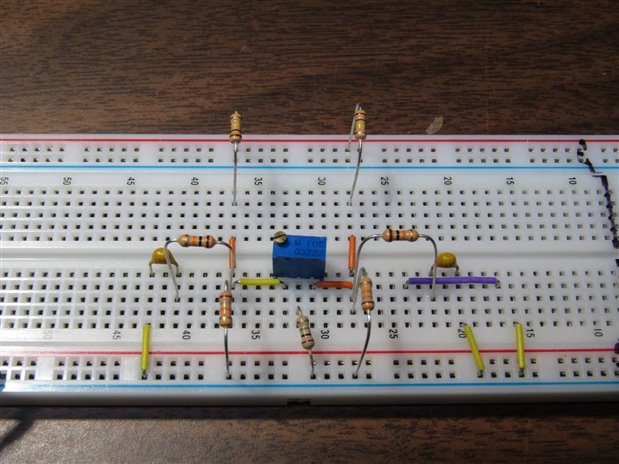
The next interface that I needed to design was the one between the Test Voltage and the Arduino's analog input (0) and the one between the Target Voltage and the Arduino's analog input (1). Since the Arduino can handle a maximum 5 volts on these inputs and since my target and test voltages may be as high as 30 volts a resistor divider seemed to be indicated. Besides just making it a resistor divider I also wanted to put a little bit of averaging into the voltage delivered to the Analog inputs so that spikes and fluctuations would not cause problems. The last thing I wanted to do was to make an effort to balance the two voltage dividers so that the voltage received by the Arduino wasn't weighted in favor of the Test or Target voltages. I wanted to be able to do this without spending hours trying to match the resistors that I chose for the dividers. Here is the circuit that I designed, bread boarded and tested out.
And the Schematic to go along with it.

Since I am only a Technician and not an Engineer I have special permission to design empirically. The balancer with the 1 meg trimmer and center leg to ground through another 1 meg resistor was what it took to balance the two sides. No calculations needed. To test this I put the same 30 volts on the Target Vin and the Test Vin. I then put my millivolt meter between "To Analog (0)" and "To Analog (1)". I next adjusted the 1 meg trimmer until I had 0 volts on the meter. This told me that my voltage dividers would deliver the same voltage to analog (0) and (1) if the same voltage was provided at Target Vin and Test Vin. To provide a little stability to the output voltage I have a 10K resistor supplying a 100 nF capacitor before it is sent to the Analog inputs.
While I didn't include it in this discussion I will also have to have a connection point to tie the Volt Meters into the circuitry. Each volt meter will need a +9 volt feed, a ground and then the voltage sense line will go back to the Target and Test voltages. The present plan is to make an Arduino shield board that will contain the two interfaces as well as the meter connection points.
If anyone can see anything that I have done in these interfaces that has "problem" written on it your input would be appreciated.
John
Top Comments