element14 Community
element14 Community
    Register Log In
  • Site
  • Search
  • Log In Register
  • About Us
  • Community Hub
    Community Hub
    • What's New on element14
    • Feedback and Support
    • Benefits of Membership
    • Personal Blogs
    • Members Area
    • Achievement Levels
  • Learn
    Learn
    • Ask an Expert
    • eBooks
    • element14 presents
    • Learning Center
    • Tech Spotlight
    • STEM Academy
    • Webinars, Training and Events
    • Learning Groups
  • Technologies
    Technologies
    • 3D Printing
    • FPGA
    • Industrial Automation
    • Internet of Things
    • Power & Energy
    • Sensors
    • Technology Groups
  • Challenges & Projects
    Challenges & Projects
    • Design Challenges
    • element14 presents Projects
    • Project14
    • Arduino Projects
    • Raspberry Pi Projects
    • Project Groups
  • Products
    Products
    • Arduino
    • Avnet Boards Community
    • Dev Tools
    • Manufacturers
    • Multicomp Pro
    • Product Groups
    • Raspberry Pi
    • RoadTests & Reviews
  • Store
    Store
    • Visit Your Store
    • Choose another store...
      • Europe
      •  Austria (German)
      •  Belgium (Dutch, French)
      •  Bulgaria (Bulgarian)
      •  Czech Republic (Czech)
      •  Denmark (Danish)
      •  Estonia (Estonian)
      •  Finland (Finnish)
      •  France (French)
      •  Germany (German)
      •  Hungary (Hungarian)
      •  Ireland
      •  Israel
      •  Italy (Italian)
      •  Latvia (Latvian)
      •  
      •  Lithuania (Lithuanian)
      •  Netherlands (Dutch)
      •  Norway (Norwegian)
      •  Poland (Polish)
      •  Portugal (Portuguese)
      •  Romania (Romanian)
      •  Russia (Russian)
      •  Slovakia (Slovak)
      •  Slovenia (Slovenian)
      •  Spain (Spanish)
      •  Sweden (Swedish)
      •  Switzerland(German, French)
      •  Turkey (Turkish)
      •  United Kingdom
      • Asia Pacific
      •  Australia
      •  China
      •  Hong Kong
      •  India
      •  Korea (Korean)
      •  Malaysia
      •  New Zealand
      •  Philippines
      •  Singapore
      •  Taiwan
      •  Thailand (Thai)
      • Americas
      •  Brazil (Portuguese)
      •  Canada
      •  Mexico (Spanish)
      •  United States
      Can't find the country/region you're looking for? Visit our export site or find a local distributor.
  • Translate
  • Profile
  • Settings
Personal Blogs
  • Community Hub
  • More
Personal Blogs
John Wiltrout's Blog Reverse Engineering an Alarm Siren Module
  • Blog
  • Documents
  • Mentions
  • Sub-Groups
  • Tags
  • More
  • Cancel
  • New
  • Share
  • More
  • Cancel
Group Actions
  • Group RSS
  • More
  • Cancel
Engagement
  • Author Author: jw0752
  • Date Created: 17 Jan 2015 7:42 AM Date Created
  • Views 1818 views
  • Likes 4 likes
  • Comments 23 comments
  • circuit_board_to_schematic
  • reverse_engineering
Related
Recommended

Reverse Engineering an Alarm Siren Module

jw0752
jw0752
17 Jan 2015

One of the things that I enjoy doing is taking a small one or two sided circuit board and creating a schematic of it. Today I have a circuit board from a 105 db piezo siren for which I am going to create a schematic.  Here is the Module.


       imageimage


The first step is to get some paper and choose a starting point. In this case I picked the output transformer and then worked my way back. As you can imagine the board must be flipped back and forth and ones perspective must constantly shift from topside to mirror image and back. The resistors must be read and measured if they can not be seen. This is also done with the capacitors. On this board the identification of the small green mylars were face to face and so one had to be removed to determine the value. When the rough draft of the schematic is finished it is never very pretty. Here is my rough draft.


image


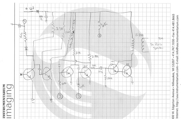
This is obviously not very good or very clear. In order to not put too many line on this draft the ground line was replaced with ground symbols and one junction point was labeled #3 and a second junction point was labeled *. What happened to #1 and #2? I am not sure it just seemed ok at the time to call them * and #3. After the rough draft is finished I use it to produce a more conventional looking hand done draft. Here is what it looks like after it has been cleaned up.


image


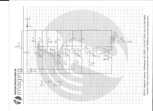
This one while still not very neat at least looks more conventional and at this point I also add component numbering. I also take close up photos of the board and label the components to match the schematic. This serves to tie things together and to make certain that I have not left anything out of my schematic. Here are the pictures and labels that correspond to the schematic.


     imageimage


Now I take all the drafts and produce a CAD drawing of the schematic to complete my file on this particular circuit.


image


This process is good exercise for the brain and gives me a very good understanding of the circuit by the time I have finished.


John

  • Sign in to reply

Top Comments

  • jw0752
    jw0752 over 10 years ago in reply to mcb1 +2
    Yes Mark you are correct on a number of counts. With the advent of multi-layer boards and SMD parts I can see the end of the trail for people like myself who like to repair circuit boards. Through the…
  • jw0752
    jw0752 over 10 years ago in reply to clem57 +1
    Hi Clem, The circuit came from a Radio Shack Alarm Siren that I was using in one of my inventions. Something went wrong and it fried. I fixed it with a new filter cap and new output transistor before I…
  • shabaz
    shabaz over 10 years ago +1
    Hi John, Thanks for the great blog post : ) This is nice, and also probably goes to show that when cost-saving, transistors may end up cheaper than a 555 circuit by a few pence/cents, and hence make more…
  • kaan3553
    kaan3553 3 months ago

    Merhaba arkadaşlar.. Başarılı çalışmanız için tebrikler.. Ben de bunu yapmak istiyorum ama d2 diyot elementinin değeri veya adı nedir? Şemalarda belirtilmemiş.. Bana yardımcı olabilirseniz çok mutlu olurum.. Teşekkür ederim.

    • Cancel
    • Vote Up 0 Vote Down
    • Sign in to reply
    • More
    • Cancel
  • jw0752
    jw0752 over 10 years ago in reply to D_Hersey

    Hi Don, Thanks for the encouragement. I will see what I can do to learn how to use the LTSpice. I am sure you are correct that it would be a valuable tool. I have seen parts of the waveform that the siren produces so if you do sim it I will see if it looks similar.

    John

    • Cancel
    • Vote Up 0 Vote Down
    • Sign in to reply
    • More
    • Cancel
  • D_Hersey
    D_Hersey over 10 years ago

    The reason they are not using the 555 is because they seek sinuate waveforms.  There are two oscillators here.  The first one seems to be a lower frequency (bigger timing components) intended to warble the second.  The last two Qs are a PA.  The four Qs to the left are in common-emmiter mode.

    Thus they are inverters and introduce a 180-degree phase-shift.  The gain of the Q's and the selectivity of the timing components allow us to meet the Barkhausen criteria at a rather specific frequency thus giving us a rather sinuate output.

    Barkhausen stability criterion - Wikipedia, the free encyclopedia


    I will sim this this weekend so we can look at waveforms.  John, you can learn LTSpice in a coupla days and have great fun while doing so.  I know I can be a scold, but this would be a wonderful conflux of your interests and abilities.  Please give it a try, its easy.


    My father was an elementary school science teacher at the beginning of his career.  He told me the hardest thing to convey to a person is that they can do it.


    I don't know that I would call these circuits vibrators.  Vibrators have something like a comparator which cause a state change in the controller.  These are feedback oscillators, a different devil.  Their characteristic output form is sinuate.  A vibrator will have an exponential ramp for a waveform, typically.  One controller is a continuous fn, the other discontinuous.


    f(x) - f''(x) = 0.  For all oscillators.


    Feedback oscillators, relaxation oscillators:

    Electronic oscillator - Wikipedia, the free encyclopedia

    • Cancel
    • Vote Up 0 Vote Down
    • Sign in to reply
    • More
    • Cancel
  • jw0752
    jw0752 over 10 years ago in reply to shabaz

    Hi Shabaz, Thank you , I am honored by your bookmark. The siren wavers up and down at about 1 cps with a very raspy main tone. Of course at 105 db  one quickly reaches for ear protection.

    John

    • Cancel
    • Vote Up 0 Vote Down
    • Sign in to reply
    • More
    • Cancel
  • mcb1
    mcb1 over 10 years ago in reply to jw0752

    jw0752

    John

    I will try to fix things that probably should just be thrown away

    Unfortunately we have produced a throw away society, and I'm not convinced we are any better for it.

    Price is the aim, rather than reliability and good design, which doesn't help make better Engineers IMO.


    Nice story .... imageimage


    Mark

    • Cancel
    • Vote Up 0 Vote Down
    • Sign in to reply
    • More
    • Cancel
>
element14 Community

element14 is the first online community specifically for engineers. Connect with your peers and get expert answers to your questions.

  • Members
  • Learn
  • Technologies
  • Challenges & Projects
  • Products
  • Store
  • About Us
  • Feedback & Support
  • FAQs
  • Terms of Use
  • Privacy Policy
  • Legal and Copyright Notices
  • Sitemap
  • Cookies

An Avnet Company © 2025 Premier Farnell Limited. All Rights Reserved.

Premier Farnell Ltd, registered in England and Wales (no 00876412), registered office: Farnell House, Forge Lane, Leeds LS12 2NE.

ICP 备案号 10220084.

Follow element14

  • X
  • Facebook
  • linkedin
  • YouTube