


One of my favorite activities is salvaging electronic parts from old equipment. I am always in search of interesting components so that I can take the process one step further and explore, experiment and learn.
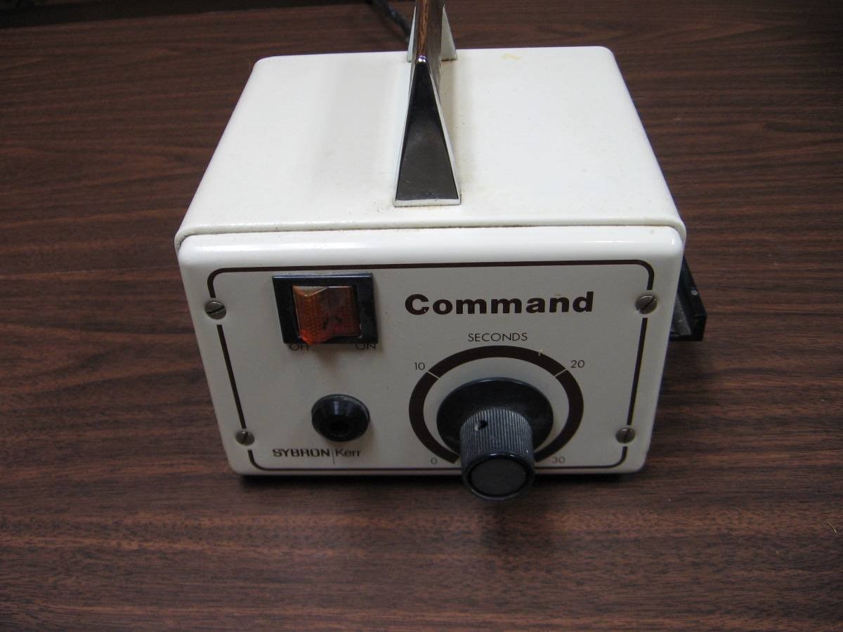
This time I was taking apart a Command Dental composite cure light. This unit has a very bright halogen light that the dentist directs, to the putty like composite filling material he has just placed inside a cavity, using a fiber optic cable. When the light strikes the material it causes it to change from a putty like plastic to a very hard plastic. There is a timer circuit in the unit and this is the main target of my salvage effort. Incidentally this is old technology and not likely still in use in your dental clinic.
Here is the circuit board that I have taken out of the Command Unit.

Most of the time I do not blog about these projects but this time I thought it might be interesting as the IC in the center of the picture is a very flexible Timer which is still current and available for about $0.50 from Newark Electronics. We are frequently asked questions about timers on the forum and while the old standby "555" is usually the go to choice the 4541 / 14541 will in many cases be easier to use and offer more choices. The 4541 or 14541 is also digital and actually counts clock pulses so it can be much more accurate than the 555.
Here is a link to the Farnell / Newark listing of the part.
http://www.newark.com/texas-instruments/cd4541be/programmable-timer-single-6mhz/dp/67K0089
Here is a link to a Data Sheet for the 14541 / 4541 that I used to explore the operation of the chip.
http://www.farnell.com/datasheets/1877024.pdf
Before I get into some of the experiments I want to go over the features that caught my attention.
This chip is designed to operate with a 3.0V to an 18V supply. For my experiments I used a standard 5 V breadboard supply.
The chip includes its own programmable RC oscillator with a frequency range of DC to 100 kHz. The choice of a resistor Rtc from Pin (1) and a capacitor Ctc from Pin (2) enable the internal oscillator. The formula for the resulting frequency is f = 1 / (2.3*Rtc*Ctc). If we are going to use this internal oscillator for our timer we must couple it to the clock input on Pin (3) using a resistor Rs that is approximately twice the value of Rtc. A choice of a potentiometer for Rtc will also allow you to vary the frequency. The original application of this very flexible timer in the Dental Command Cure Light used a 500K potentiometer for Rtc so that a variable time of 0 to 30 seconds could be chosen. Here is a schematic of the oscillator section of the chip taken from the Data Sheet:

The chip will also accept an external clock in which case Pins (1) and (2) are left open and the external clock signal is input at pin (3).
The output of the chip is on Pin (8) and can supply and sink current to drive several logic loads. Check the Data sheet for more specific figures as the current supplied and sunk by the output depends on the Vdd that is selected.
The output can be controlled (inverted) by the choice of a HIGH or LOW setting on Pin (9) of the chip. This will be demonstrated in one of my short videos.
The chip also has two modes that are controlled by the choice of HIGH or LOW applied to Pin (10). In the Mode selected by applying a HIGH to Pin (10) there is a continuous translation from the clock input or the oscillator of the chip to the output. *** I will explain what is meant by translation in the next section. If we apply a LOW to Pin (10) the chip operates in a single transition mode or one shot mode. This means that there will be a definite timed period between a reset (HIGH on Pin (6)) and the change of state of the output Pin(8). This is a one time transition in this mode and can only be made to repeat by once again resetting the chip. I will demonstrate this mode with a couple different settings in the short videos that follow.
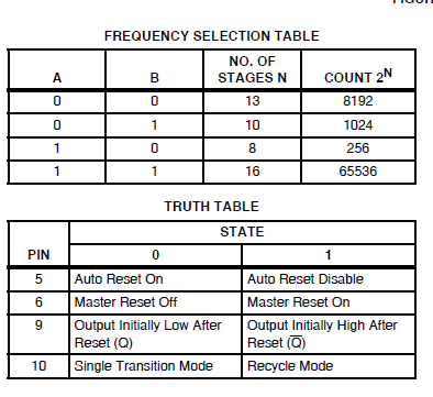
Another feature of the chip is that it has a 16 stage binary counter that acts as a frequency divider of the clock frequency. The programming for this section of the chip is on Pins (12) called "B" and (13) called "A". Our choices for HIGH or LOW on these pins will provide a choice of these 4 counter stages 2^8, 2^10, 2^13, and 2^16. ( x^y means x to the y power). Here is a snippet from the data sheet that summarizes the choices for "A" and "B" as well as the Truth table for the other programmable pins on the chip. *** When I mentioned translation above I was referring to the process of dividing the clock frequency by the counter stage to get an output frequency.
The reset for the chip is on Pin (6). LOW is enable and HIGH is reset. The oscillator and all functions of the chip stop as long as the Pin (6) is held HIGH. I have used the Digital Timer Circuit from the data sheet to set up my test circuit. A 10K resistor was added in my actual circuit to the reset Pin (6) to pull it LOW when not being reset by direct connection to the Vdd rail. I have used a suggested value of 56K for Rtc and 120K for Rs. Ctc was varied during the experiments from 1 nF to 10 nF to 100 nF in order to produce Oscillator frequencies of approximately 8 kHz, 800 Hz, and 80 Hz respectively. The logic states of "A" and "B" were also adjusted to choose different stages to direct to the output.

Diagram from the Data Sheet.
In this first video we have the oscillator running at 800 Hz and both "A" and "B" are set to LOW so we have chosen the stage 13 (n) of the counter. Pin (9) is set so that the LED tied to the Output Pin(8) is normally on. Our mode Pin (10) is LOW so our timer will act as a single shot. The data sheet tells us, in this mode configuration, with reset, the timer will count to 2^(n-1) before changing back to normal output. In this case we will have 4096 counts divided by the clock of 800 Hz. I would expect slightly more than 5 seconds. Note that since this timer is actually counting a clock signal it can be much more accurate that the RC time constant of the traditional 555. Here is the first video demonstrating this configuration. Keep in mind that not only can we control the frequency of the clock from DC to 100 kHz but we can also control the choice of the counter stages by selecting the logic state of Pins (12) and (13).
In the next experiment I have changed the oscillator frequency to 80 Hz and set the "A" and "B" logic to count to 512. Keep in mind that an "A" = LOW and a "B" = HIGH selects the 10th stage of the counter (1024 counts) but the state of the output actually changes at the (n-1) point in the count or (512). In addition I have inverted the Output on Pin (8) by setting Pin (9) HIGH. This will cause the LED to be off normally, come on for 512/80 = 6.4 seconds and then go back off until the reset on Pin (6) is again triggered by pulling it HIGH.
In this last video I have changed the mode of the timer, by pulling Pin (10) HIGH. This causes the chip to divide the clock frequency by the selected counter stage (Pins (12) and (13)) and output the resultant frequency continuously from the Output on Pin (8). In the case of this video I have chosen a capacitor such that the oscillator is producing an 800 Hz clock signal and the "A" is set LOW and the "B" is set HIGH which selects the 10th counter stage. Therefore our output frequency will equal 800 divided by 1024 or slightly shorter than 1 Hz. By choosing the Input clock frequency and then programming the correct counter stage our timer can accurately produce just about any desired Output clock frequency. Just a note here, in the first 2 demonstrations we were calculating period so we divided the selected counter by the clock frequency. Now we are calculating frequency so we must divide the Clock Frequency by the counter stage.
The last experiment that I conducted was to set the chip in the continuous mode with the clock running at approximately 8.2 kHz and the "A", "B" stage selector set to 10 ( 2^10 = 1024) so that we should have an Output of 8 Hz. Here is the oscilloscope image with Channel One tied to the clock and Channel Two tied to the Output.

My method of salvaging parts and pursuing more in depth knowledge of them by reading their Data Sheets and by performing small experiments is a lot of fun. By the time I put the part into a drawer or bin I know enough about it to reuse it in a different application. While I like building new things I can not always come up with sensible builds and the salvage and explore scenario keeps me active and learning about components continuously. The part that we looked at this time the HEF 4541 or MC14541 is not a new part. It is much the same vintage as the NE555 but the fact that it is still commercially available speaks to its application and flexibility. If you like to work with timers or use them in your designs put a few of these on your next order to Newark and have some fun playing around with them.
John
Top Comments