


Previous Shop Tips:
http://www.element14.com/community/people/jw0752/blog/2015/05/16/shop-tips--storing-hookup-wires
Up until about two years ago I did not use the bread board system to test circuits or to prototype. I had my methods and as is my nature I am slow to change. When I went back to studying electronics and trying to move my knowledge and skills a little closer to modern technology the bread board was one of the first things that I embraced.
The bread boards that are used in my shop are a board with holes spaced 1/10 of an inch apart. The top edge and bottom edge have two rows of connections colored red and blue that can be used to carry voltages and grounds along the length of the board. Between these power Rails are columns of connections separated at the center of the board. This arrangement of holes and connections makes hooking up parts very easy and once one becomes familiar with the layout it is easy to see the correspondence to the schematic.
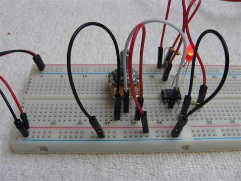
It was noted that there were two ways to hook things together. One way was to use what I would call jumper wires made of stranded wire with 22GA solid wire tips. These jumper wires come in a variety of lengths and at first seemed very acceptable. The other method was a solid 22 GA buss wire bent to just the right shape to bridge a specific distance on the bread board. These bridge wires were colored coded to their specific length and ran in size from 1/10th of and inch, in 1/10th of an inch steps, all the way to 1 inch and then there were some 2 inch, 3 inch, 4 inch and 5 inch pieces. When I bread boarded the same circuit using both systems I got these results:
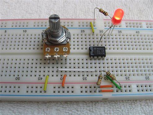
It did not take me long to decide that I liked the circuit built with the Solid Buss Bridge wire better and it wasn't just because of how neat it looked. It was noted that the Stranded Jumper wires had a lot more resistance than the buss wires. The first question that I put on the Forum 2 years ago and was answered by mcb1 involved a prototype that worked fine on the breadboard but didn't when soldered onto a circuit board. The difference was the resistance introduced by the Jumper wires. Another source of problems that come with the Stranded Jumper wires is increased undesirable inductive and capacitive coupling.
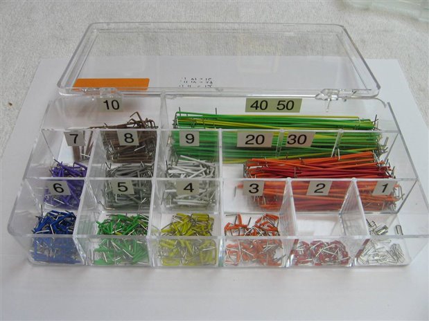
While there was still a place in my bread boarding for the Stranded Jumper wires, they were relegated primarily for use as connections to off board components or for bridging from board to board, or board to Arduino. It was noted that for 90 percent of the links needed to bread board the supplied sizes up to an inch were adequate. While supplied with the kit the 2, 3, 4, qnd 5 inch lengths were never used. Here is the shop Buss Bridge Wire kit with labels for 1/10ths of an inch.
In the rest of the blog I will let the 10ths be understood, meaning that "7" means a bridge of 7/10ths of an inch.
As more complex circuits were bread boarded there was a need for 11s and 12s. It was also convenient to have 18s which bridged the distance from upper power rail to lower power rail. If the circuit, that was being bread boarded, demanded higher current these bridges reinforced the current capacity.
Finally the purpose of the 20s, 30s, 40s, and 50s became apparent to me. They were raw material to cut and build whatever length Buss Bridge was needed. If you haven't guessed already I like to plan and organize things as much as I like electronics so it became a fun project to expand the sizes of the Buss Bridges in the shop kit by 1/10 inch increments up to 29. Here is my procedure for making a new Buss Bridge.
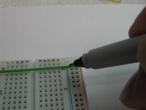
In this case I am going to make an 18 out of a 50. One side of the 50 is plugged into the blue ground rail at the other side of the board and I make a mark where I want to remove insulation and bend. Enough extra wire is allowed past the mark for the bared wire that will be bent at a right angle.
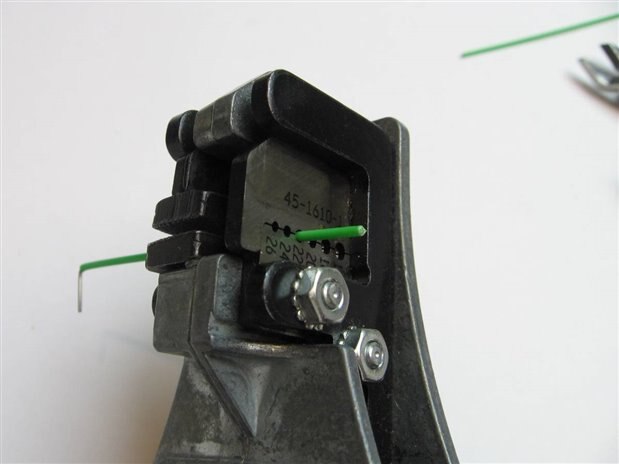
The insulation from the mark to the end is stripped off.
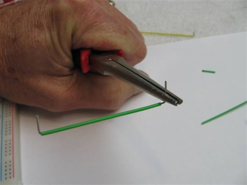

The wire is bent to a 90 degree angle and tested in the bread board.
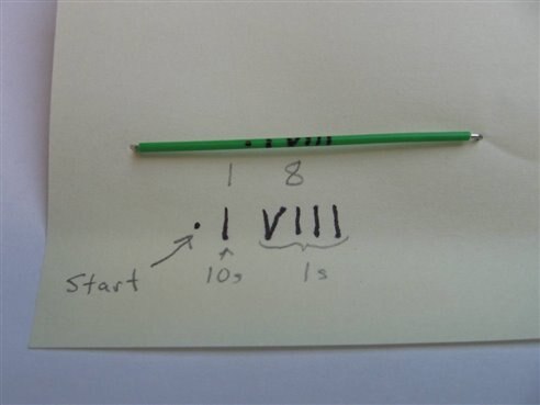
My next challenge was to devise a system to mark my new sized wires. Up to the 10 size we had color to tell us the size but all the larger lengths were being made from the 4 colors used by the 20, 30, 40, and 50 lengths. Color would no longer be relevant. Testing revealed that by using a very sharp permanent marker it was possible to make the following distinguishable marks: " . ", " I ", and " V ". My system would involve a DOT to orientate the beginning of the sequence of marks. Next, spaced to the right would be a " I " for 1 or a " II " for 2. Finally spaced to the right would be the normal Roman Numeral sequence for the numbers for 1 to 9. ( I, II, III, IV, V, VI, VII, VIII, VIIII ). Here is how I marked the 18 wire that was just made and an example of other lengths:

A compartmentalized fishing tackle box made a good place to store the new lengths:
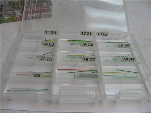
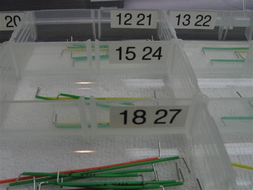
Note that two sizes have been put in each bin but always with enough of a difference in their sizes to make it obvious which is which.
Here is a circuit that was bread boarded after all the sizes were cut and easily available:
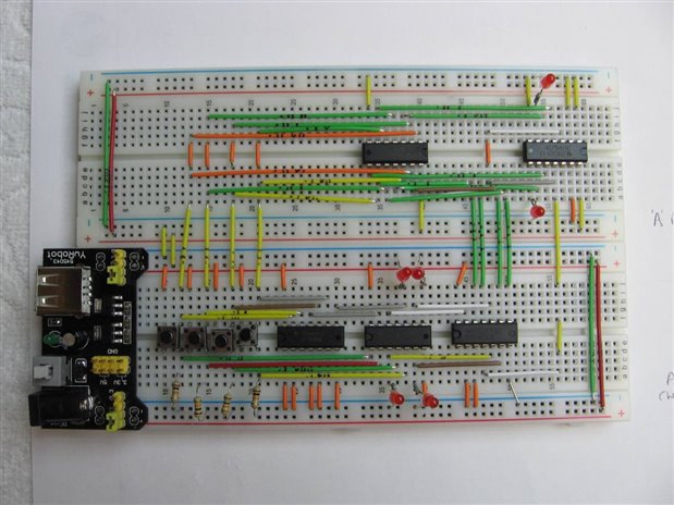
This is the same circuit as illustrated on Page 124 of Charles Platt's "Make: More Electronics".
Since the following ideas are very simple and related I will include them in this blog. Often it is necessary to put a TO-220 case transistor or voltage regulator into the bread board. The dimensions of the legs however do not fit well, too big. It is a concern that if they are forced the connection pins below the holes will become strained and not hold future wires securely. By taking a piece of header with long leads and cutting it into a triple it can act as an adapter for the TO-220 device.

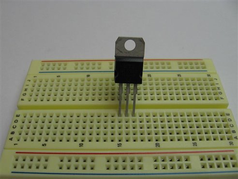
Header cut to a Triple and TO-220 Regulator that doesn't easily fit into the bread board.
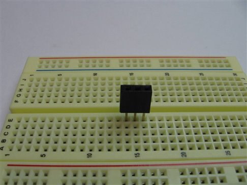

The Header easily fits into the bread board and the TO-220 easily fits into the Header.
If the TO220 is handling some current perhaps a clip on heat sink is in order. I have shown this clip which looks like a small empty money clip in a previous blog but here it is again:
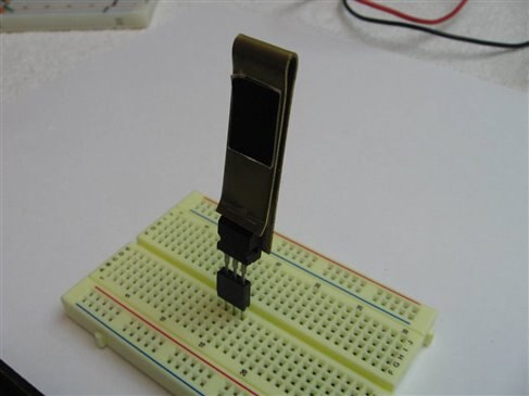
The TO-220 in the Header with the Heat Sink clip on top. The black tag is thermally sensitive and says "HOT" when the temperature of the clip gets above 50 degrees C.
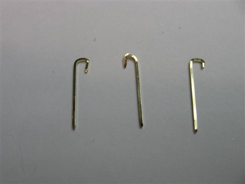
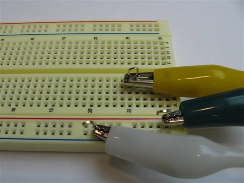
Finally we have these little hooks that are used as connection points or test points on the bread board.
This is the 5th Shop Tips Blog. I want to thank all of you who have commented on my blogs and also those of you who have looked at or Liked them without commenting. Positive and negative critique is always appreciated. We learn by making mistakes and having our ideas challenged.
Thanks John
Top Comments