


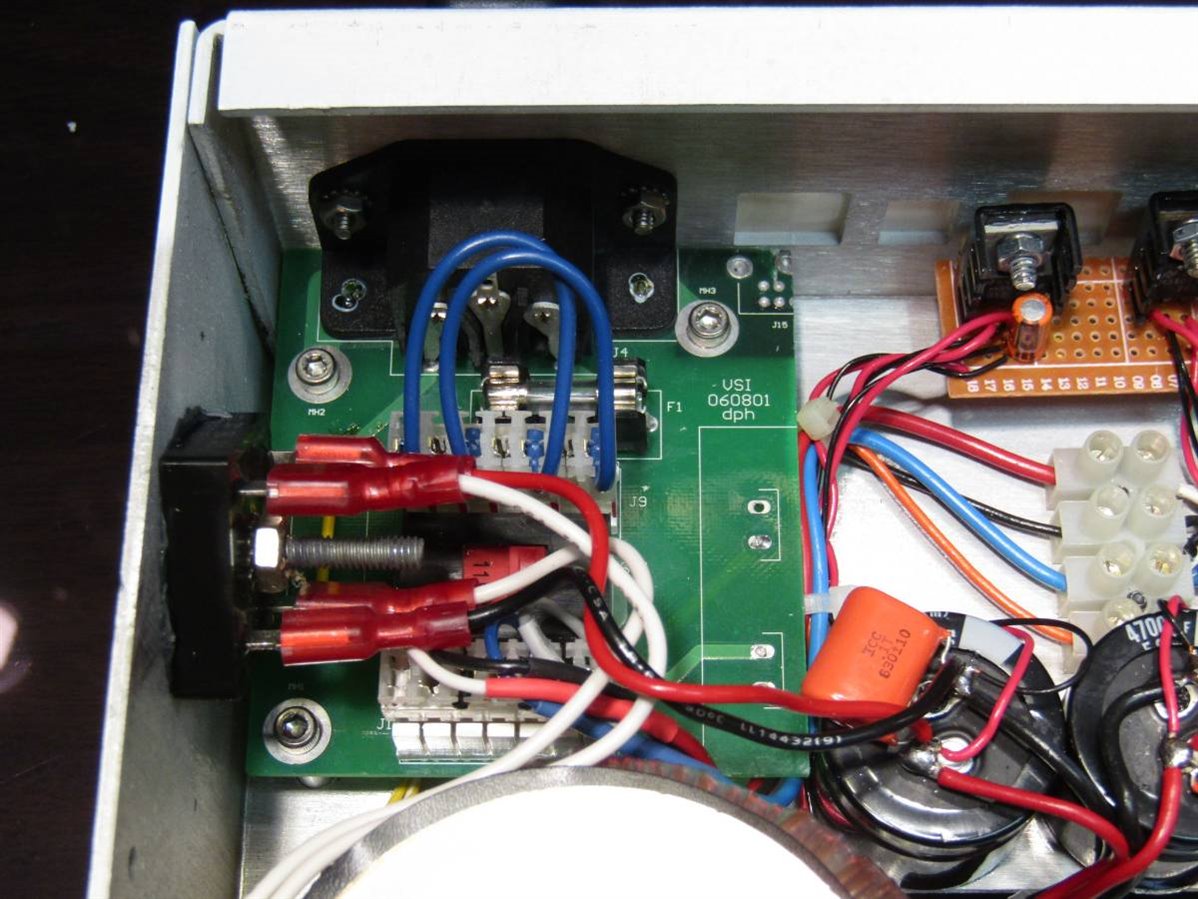
A couple weeks ago I asked the forum for some ideas for a Coarse/Fine adjustment circuit for a basic bench power supply that I was going to build. While the power supply is nothing special and the build was rather routine I thought it might be fun to show you how the final product turned out and how I incorporated the Coarse and Fine circuit into the unit. Here is a picture of the inside of the completed power supply.

The unit has a nice project box that was originally a intra oral dental camera. Since I had two of these units I was able to salvage the nice toroid transformers from each unit so that I would have two isolated DC power channels on the outputs. The small green board in the back left corner was part of the original unit's circuit board that has been modified and retained as a line power entrance for the unit. Here is a close up of that board.
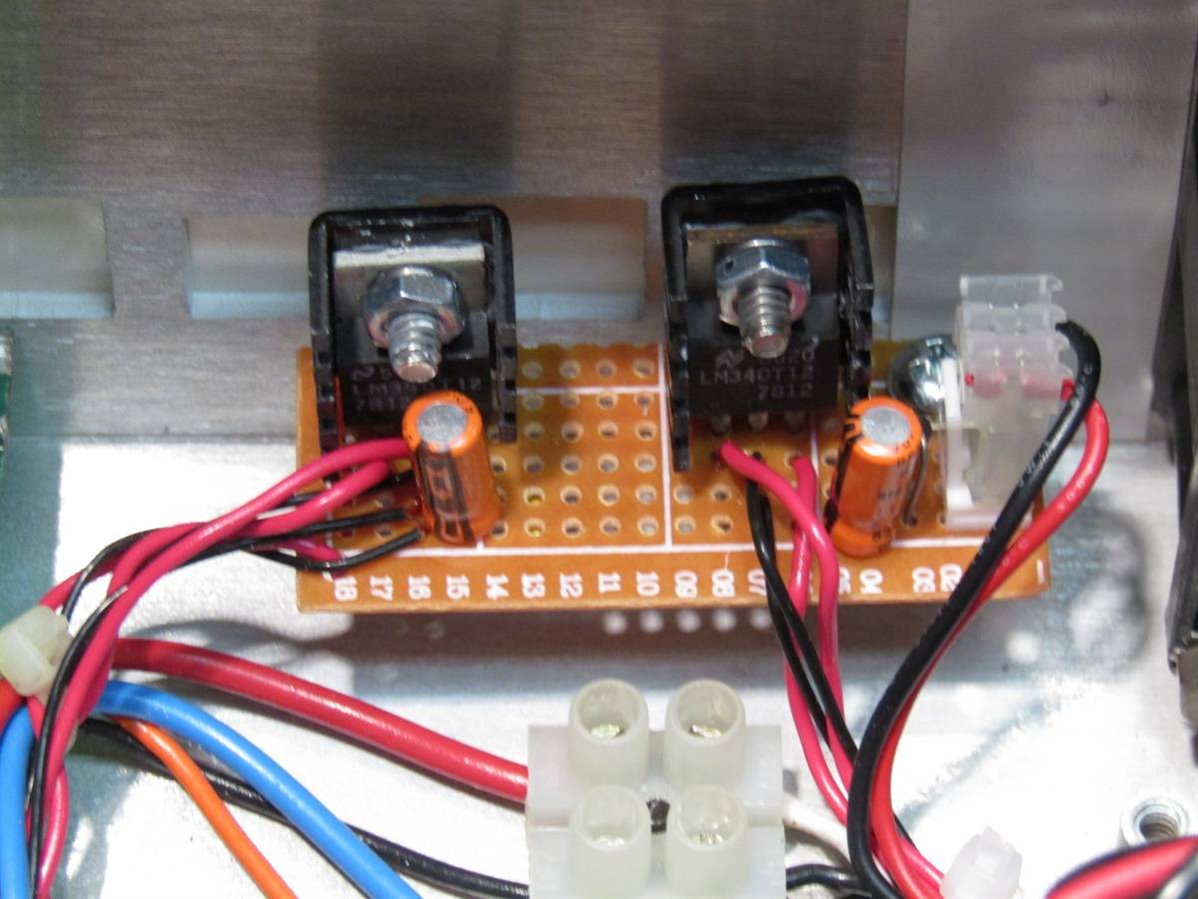
The board and the toroids are capable of switching from 120 VAC to 240 VAC input power though in my area, at least, only the 120 VAC option will be used. Along with the toroids from the original dental cameras I have also retained the bridge rectifiers and the filter caps. I will need 12 volts to power the LED meters that I have chosen for the front control panel and I will also need a voltage source for the power on LED and a small cooling fan. To do this I built a 7812 based linear regulator circuit for each channel. Besides the channel's meter this circuit will power the LED on one side and the fan on the other. Here is a better picture of the voltage regulator circuit:
Now is the point where I take a short cut and use a couple of Chinese DC to DC converters that I purchased for $4.00 each. Amazingly these came for that price including shipping. Every time I order some of these cheap items and get the shipping included I suspect that it may be the last time. It doesn't make sense how anyone can make a profit doing it this way. Here is a close up of the converter:
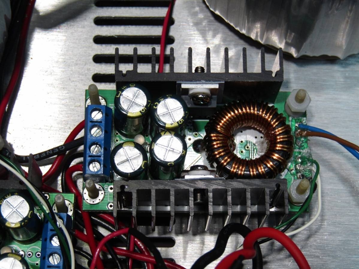
This little DC converter is based on an XL4016 chip and is capable of input up to 36 volts and output of 1.2 volts to 35 volts at 8 amps. Since my transformers will only produce unregulated 27 volts my upper range for this power supply will be limited by the voltage drop of the transformers under load. Experiments have shown me that I can expect 24 volts at 1 Amp and 20 volts at 5 amps final output from the unit. I was a little disappointed that I can not lower the output below 1.2 volts but this is more of an aesthetic complaint as opposed to a practical one. Most of my experiments are at 3.3 volts and above and should I need a lower voltage for some reason I could always use another means to get it. The DC/DC converters came with small multi-turn 10K trimmers which I have removed and installed wiring harnesses to attach to the control panel potentiometers. Here is a schematic of the circuit I finally settled on for my coarse / fine control. Since the converter only looks at a variable resistance between 0 and 10K to control the output voltage I have tried to stay close to that parameter in the control design.

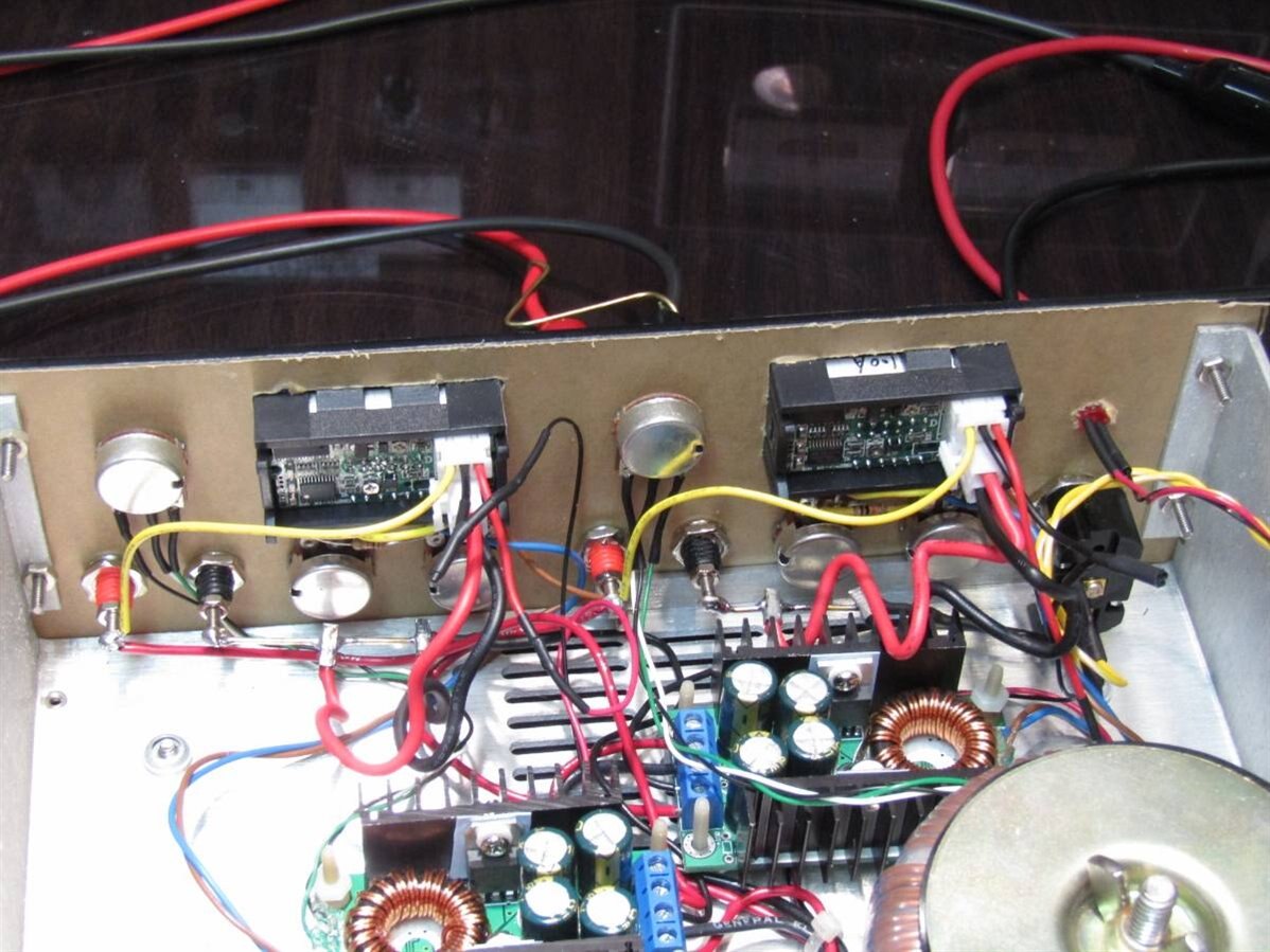
Here is a picture of the inside of the control panel but unfortunately it doesn't do a very good job of showing the wiring to the controls. The Coarse Potentiometer will change the output voltage from 1.2 volts to 27 volts over it's 270 degree sweep while the Fine Potentiometer will change the voltage output by at the most plus or minus 1 volt over its 270 degree sweep. The fine control is more effective for voltage levels in the middle of the range and its effectiveness drops as the coarse control approaches its limits.
The meters come with very large shunt bars to be used to measure up to 100 amps but this would not be practical for this unit so it was necessary to make and calibrate some shunts more practical to this application. I used some 16 GA brass wire and soldered the leads from the ammeter to it. With a lab ammeter in series I was able to move and resolder the meter leads back and forth on the brass wire until I got the meter reading to match the Lab Meter. If you follow the large black and red wires from each meter you should be able to spot the brass shunt wires for each channel. Here is a picture of the unit completed and assembled:
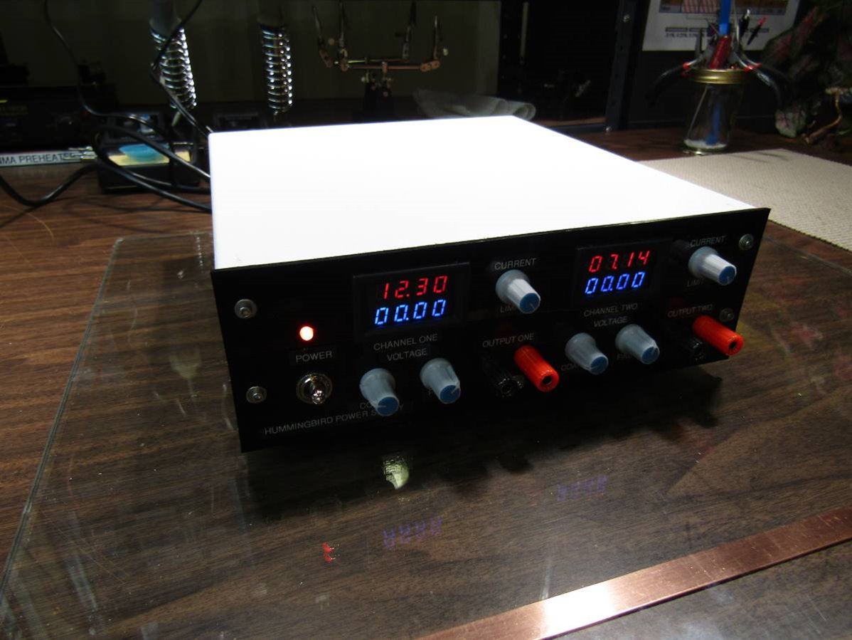
I have also made a short video of me using the fine controls to zero in on a specific voltage on each channel. Besides my time which nowadays is practically worthless I have about $35 dollars invested in this unit thanks to my sons for the donation of the two scrap dental camera units and cheap Chinese electronic modules and meters.
I also want to thank my friends on E-14 for their excellent and inspiring suggestions for adding the fine voltage control.
John
Top Comments