


In this post I provide details about the signal format used to program the WS2811 RGB LED driver. These details are needed to program appropriate pulse trains into the Agilent 33522B. I will also explain an interesting anomaly I discovered while experimenting with the LED strings I purchased for this project.
Pulse parameters for the WS2811
Two pulses are understood by the WS2811: A pulse that represents logic 0 and a pulse that represents logic 1. The timing parameters for these pulses are shown in the table below.
| Pulse Type | tON | tOFF |
|---|---|---|
| Logic 0 | 500 ns ±150 ns | 2.0 μs ±150 ns |
| Logic 1 | 1.2 μs ±150 ns | 1.3 μs ±150 ns |
These values produce a constant bit cell-time of 2.5 μs for logic 0 and logic 1 cells. At 2.5 μs/bit, the bits will be sent to the LED strings at a rate of 400,000 bits/s. The WS2811 specifications call this the FOSC1 operation frequency. The device is also capable of operating at 800,000 bits/s (called FOSC2 in the specs). During tests to validate the ±150 ns tolerance on pulse widths I discovered that the availability of a high speed mode means the tolerances in the table above have to be interpreted carefully. More on this later.
The Absolute Maximum Ratings table in the spec sheet lists power supply voltage as +6.0VDC ∼ +7.0VDC. For all experiments described below the supply voltage was set to +6.0 VDC.
Now, back to the pulse train composition. Each device in the LED string contains a WS2811 controller, a red LED, a green LED and a blue LED. The WS2811 allows 8-bits of intensity control data for each of the three LEDs. So, each WS2811 will strip off the first 24-bits of data it receives to control the three LEDs attached to it. All remaining bits are passed on to the adjacent device in the string. The specs in the WS2811 show the 24-bit data format as follows:
| b0 | b1 | b2 | b3 | b4 | b5 | b6 | b7 | b8 | b9 | b10 | b11 | b12 | b13 | b14 | b15 | b16 | b17 | b18 | b19 | b20 | b21 | b22 | b23 |
|---|---|---|---|---|---|---|---|---|---|---|---|---|---|---|---|---|---|---|---|---|---|---|---|
| R7 | R6 | R5 | R4 | R3 | R2 | R1 | R0 | G7 | G6 | G5 | G4 | G3 | G2 | G1 | G0 | B7 | B6 | B5 | B4 | B3 | B2 | B1 | B0 |
Where "bn" is the bit number within a 24 bit sequence, "Rn" indicates the bit position for RED bits, "Gn" indicates the bit position for GREEN bits and "Bn" represents the bit position for BLUE bits. From this table one would assume the bit pattern for the three LEDs is organized in the traditional R-G-B (Red-Green-Blue) pattern. As is often the case, assumptions can be wrong. The assumption made here, by the writer of the WS2811 spec, is that the end user of the WS2811 will connect a RED LED to the OUTR pin, a GREEN LED to the OUTG pin and a BLUE LED to the OUTB pin. Nothing prevents the end user from connecting whatever colour LED they desire to each of the output pins. Perhaps a better description of the output pins would have been OUT1, OUT2 and OUT3. If this more generic nomenclature had been used, some of the confusion I encountered while experimenting would have been avoided.
Generating simple test patterns in Agilent's BenchLink
The plan now is to generate three simple pulse trains. One each for minimum brightness RED, GREEN and BLUE. Each pulse trains will consist of 24 bits. To generate minimum brightness on the desired LED we will put a single logic 1 in the least significant bit position for the desired LED and place logic 0 in all other bit positions. As an example, the bit pattern for minimum brightness on the LED connected to OUTR look like this:
| b0 | b1 | b2 | b3 | b4 | b5 | b6 | b7 | b8 | b9 | b10 | b11 | b12 | b13 | b14 | b15 | b16 | b17 | b18 | b19 | b20 | b21 | b22 | b23 |
|---|---|---|---|---|---|---|---|---|---|---|---|---|---|---|---|---|---|---|---|---|---|---|---|
| 0 | 0 | 0 | 0 | 0 | 0 | 0 | 1 | 0 | 0 | 0 | 0 | 0 | 0 | 0 | 0 | 0 | 0 | 0 | 0 | 0 | 0 | 0 | 0 |
If the LED connected to OUTR is in fact a RED LED, this pattern will produce minimum illumination on the RED LED and turn off the other tow LEDs in the package.
Let's see what happens when we generate the bit pattern above, copy it to the Agilent 33522B and drive the LED string. All of the work shown below was accomplished with Agilent Benchlink Waveform Builder Basic, because the demo period on my full version expired long ago.
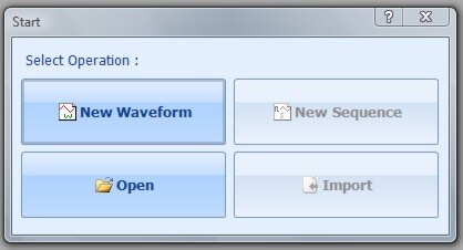
After starting Benchlink, select New Waveform:
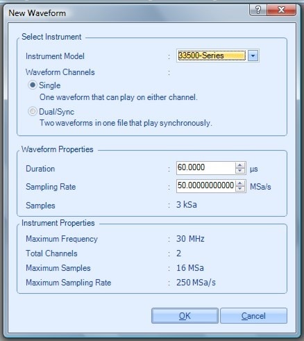
Then, in the New Waveform dialogue, set up a single channel waveform with a 60 μs duration (2.5 μs/bit X 24 bit = 60 μs).
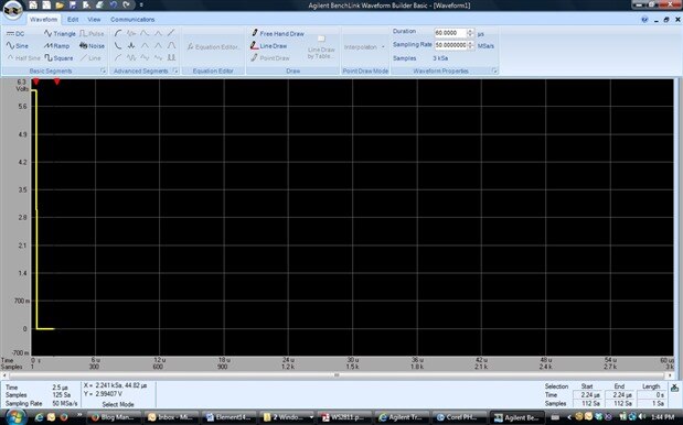
A blank waveform creation screen pops up. This is where a graphic of the desired waveform pattern will be built.

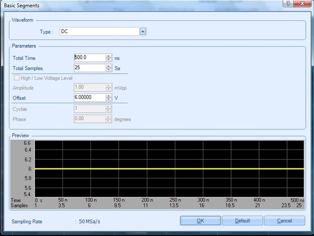
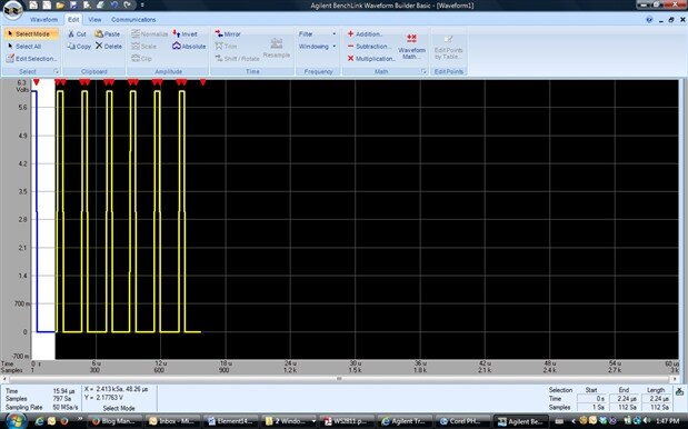
The pattern for the first LED is seven logic 0 pulses followed by a logic 1 pulse. I'll build a single logic 0 pulse, then use cut and paste to duplicate six more and tack on a logic 1 at the end of this sequence. First, select DC from the Waveform tab, then select a 500 ns duration with a +6.0 V offset.
The result will be a short piece of +6.0 VDC on the overall waveform builder view. Returning to the DC segment dialogue, I'll add 2.0 μs of 0.0 V at the end of the waveform. A single logic 0 pulse is thus described.
Using copy and paste tools, make six more logic 0 pulses. The waveform now looks like this:
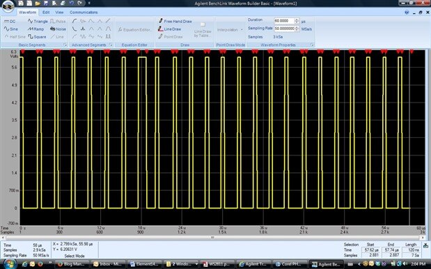
Again, using the DC component from the waveform tab, build a single logic 1 pulse with information from the timing parameters table above, then copy and paste in 16 logic 0 pulses to turn off the other two LEDs in the device. The full 24 bit pattern looks like this:
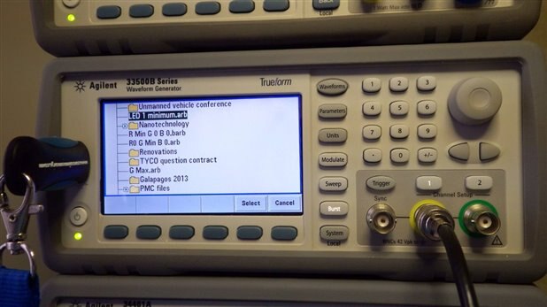
For this example, I saved the waveform, called "LED 1 minimum" to a USB memory stick and moved the stick over to the front panel USB socket on the Agilent 33522B. The photo below shows the USB thumb drive inserted into the 33522B. From the front panel I selected "Waveforms" then on the soft key menu, selected ARB, then Arbs (seems redundant, but that is the correct sequence), then "Select Arb", which brings up a file listing of the USB memory stick. With the desired filename selected, press Select, and the file loads into the Agilent 33522B.
There is now one copy of the pulse train that illuminates the first LED at minimum brightness in the memory of the 33522B. Using the Burst output mode, that single copy can be repeated any number of times to light up more LEDs in the string. I have 4 m long strings, each with 60 devices/m. That makes for 240 devices/string. Two strings together makes 480 devices. Let's start with a burst of 10 copies. That should light up exactly the first 10 devices in the string. The video below shows the bench set up including the various instruments used to observe system behaviour.
Finally, for this blog entry, the video below shows the 33522B being triggered to produce 10 copies of the LED 1 minimum waveform. That lights up the first 10 devices in the string with minimum illumination on the first LED in each device. Turns out the first LED in each device is a green LED, not a RED LED, so the WS2811 spec needs to be interpreted carefully, based on how the device manufacturer set up their devices.
Next time, I'll check out the current draw for each LED colour and see what happens to VDD at the end of the strings. I'll also look at timing tolerance and see if I can create dynamic light patterns using the deep memory of the Agilent 33522B
Cheers,
Mark
