

I did a preliminary blog about this on May24th and promised more when I got the boards. It's a bit of a mixed story some good news, and some less good.
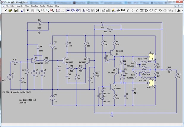
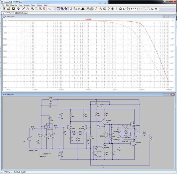
I'm posting the LTSpice model and the schematic again , to avoid endless cross referring for any one who wants to really get into the detail which will follow.

This is exactly the same schematic as I posted earlier.
The idea of the power amp is that it can work effectively from DC to 2MHz with a 30V pk-pk output from 50 ohm source with no load. This causes some problems because it demands precision DC performance (which is easy to get form an integrated op amp but very hard to get any other way) and a high output voltage and slew rate with peak output current of 400mA - which is not available form op amps.
My solution is to use a precision op amp as the front end and a discrete transistor amplifier to do the heavy work. It worked OK in simulation but the real performance so far is not quite where I want it to be.
There seems to be quite a bit of interest in how people build stuff so I'm going to provide some pictures and explanation of how I do it.
The boards were designed using Easy PC and made by PCBCart in China. 5 boards cost me £135.40 (including the solder paste stencil) , they took about 10 days to get here, half of which was shipping time.
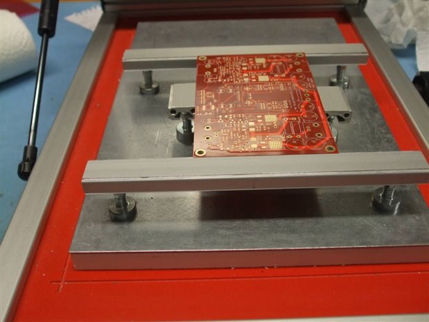
A board on the solder paste screen print machine.
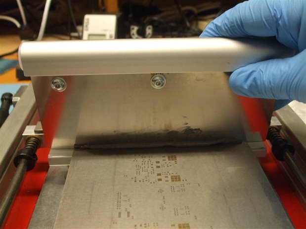
The precision solder paste application system in action !
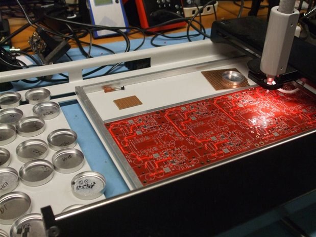
4 boards on the manual pick and place machine ( you slide the picker about by hand, pick the bits out of a little pot and place them, one at a time.)
Boring and slow but much quicker than tweezers and much cheaper than a full on machine.
I have a small Chinese fully automatic machine but it isn't worth setting up a board like this to make 4.
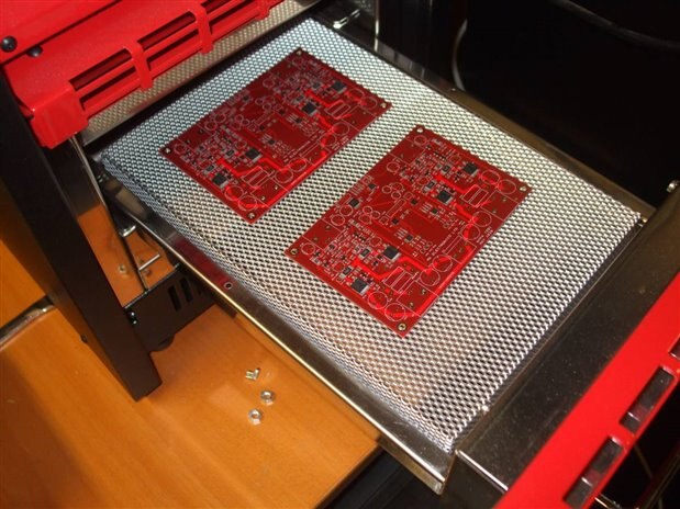
2 boards about to be reflowed.
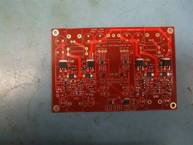
With all the surface mount parts safely soldered on.
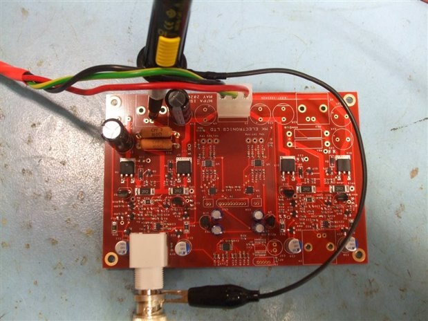
Initial testing, only enough of the through hole bits to make it (sort of) work.

Re-work - change 8 Rs and Cs. I bought the nice little board holder from Amazon - only £6.99.
https://www.amazon.co.uk/gp/product/B01MRAEY6M/ref=ppx_yo_dt_b_asin_title_o00_s00?ie=UTF8&psc=1
When I first powered up the board it was obvious that there was a problem - almost any disturbance, including touching the DMM probe on the output and it would burst into oscillation at about 700kHz and draw lots of current. I had set a 300mA current limit on the +/- 20V supply and it would pull this down to +/- 10V.
I had a bit of a re-think and some LT Spice fiddling and came up with some new component values.
This spice model has several component changes compared with the one I posted in May.
These changes did the business to the extent that it doesn't lock up and more or less behaves.
Some things are quite good:
DC offset (no load) is about 40uV. (The op amp actually used is a TI OP192 - not the ADA4622.)

The THD at 100kHz as measured by Picoscope 5444 is about 0.07%.
It drops a little with no load so I think this is a realistic figure. I've seen less than 0.04% with the same measuring set up.
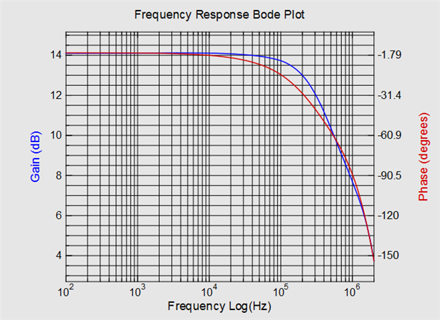
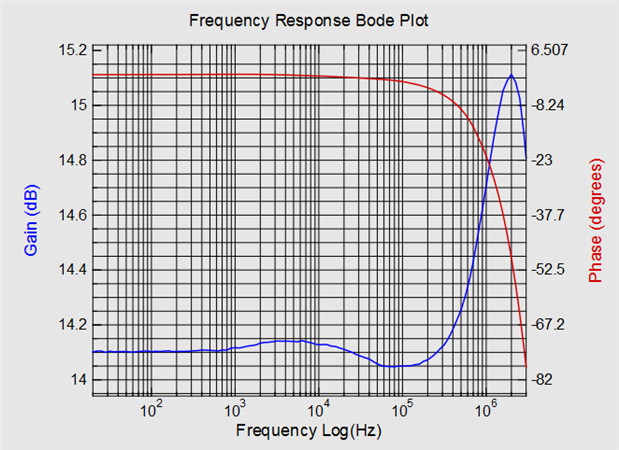
The frequency response is dominated by the R20/C9 filter, just about acceptable for up 10 100kHz operation.
The response was measured using the Picoscope 5444 with the excellent free response plotter written by one of Pico's customers.
Unfortunate it does not work with the latest version of the Picoscope software.

This is the response from +ve input of U3, that horrible peak gives a warning of trouble to come !
The LTSpice model does peak a bit but only by half the amount.
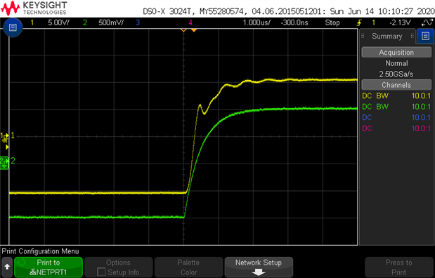
It does not like pulse inputs.
The yellow trace is the output into a 50ohm load, the green is the signal au U3 +ve input.
The LTSpice model doesn't do this.
By a good bit of fiddling with the LTSpice model and measuring the board I think I have worked out what is going wrong.
When the pulse starts there is some delay while the signal propagates though the amplifier, the output lags the input signal and quite quickly
Q1 turns on quite hard, Q3 turns on very hard and the output slews +ve as fast as it can. After a while it catches up with demand and the feedback
tries to turn off Q1, and subsequently Q3 - the nasty peaky response rings away and it sort of staggers along for the next couple of micro seconds.
Q3 can source quite a lot of current, maybe 40mA or so and can pull the output up much faster than Q4, which is a 6mA current sink, can pull it down.
This is why the negative going pulse edge is much cleaner but slow (I've not shown it here.)
But LTSpice doesn't show this behavior - I got it close to reality by putting a large (1nF) cap from Q4 collector to ground.
The problem seems to be that the models for the output transistors are totally wrong !
I did some experiments and found that the MJD112 model set up as a high current emitter follower goes much faster than a 2SCR573D, although
on paper the MJD112 is actually 13x slower !!
So, I have ordered some replacement output devices which should be a lot faster - they look great in LTSpice 
I'll add to this blog when I get some results from them.
Right now the amplifier shows promise (distortion and offset), but not as much as I would have liked.
MK
UPDATE 20/06/2020
I've replaced the output power darlingtons with some much faster single transistors. I used 2SC4027T and 2SA1552S, these are not quite
a perfect pair - would have been better with both of them in the T gain selection so the PNP has lower gain.
The first thing was to simulate and re-tune again - since the ON transistor models are so rubbish I just used the nearest models in LTSpice.
It was much easier to get a nice frequency response and a good transient response:
Once it was built it behaved much better in real life as well (for this trace I kept the input filter of 1k/470pF the same:
So far so good - a huge improvement on the darlington output version.
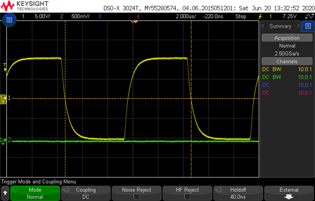
So out with the input filter, I changed it to 1k/47pF and got this:

This is quite a respectable 100kHz square wave.
The Keysight won't measure distortion or slew rate so over to the Picoscope:

I did try at first with R5 and R4 at 100ohms to reduce the power in the TO92 case driver transistors but the falling slew
rate was only about 38V/us.
(Notice the Picoscope amplitudes are half that seen on the Keysight because I have a 50 ohm load on the Pico but 1M on the Keysight)
Reducing R5 to 51ohms gets the slew rates about equal in each direction and is what produced the scope traces -
(I know the LTSpice model has 47 but I was sorry for those poor little transistors (Q3 and Q4) )
The slew rate should be OK for 2MHz - the falling edge is managing about 70V/us and for 2Mhz we need 2 * pi * F * Vpk = 2 * pi * F * 5 = 63V/us.
The distortion is pretty much unchanged at 0.08% at 100kHz (0.06 without load) The amp now works well enough to measure the distortion at 1MHz (about 2%).
The slew rate still isn't fast enough to say that it works at 2MHz properly - the distortion rises to about 4%.
All the distortion figures are for 10Vpk-pk into 50 ohms ( so the amplifier is doing 20V pk-pk into 100ohms).
It should be possible to tune things up a little better so as to increase the feedback and reduce the distortion at high frequencies.
The frequency response is pretty good now,
This is with the 1k/47pF input filter.
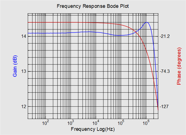
And this is without, the peaking is now only 1dB rather than 5.
A bit more testing and tuning is needed but the amplifier is certainly good enough to use up to 100kHz and at a pinch
maybe to 1MHz.
MK
Top Comments
-

shabaz
-
Cancel
-
Vote Up
+1
Vote Down
-
-
Sign in to reply
-
More
-
Cancel
Comment-

shabaz
-
Cancel
-
Vote Up
+1
Vote Down
-
-
Sign in to reply
-
More
-
Cancel
Children