Time is cheap - Investigating low cost 2nd hand oscillators from China
There have been a couple of projects and discussions about time and clocks on E14 lately:
Digital Clock
Building My Dream Digital Clock: DIY 7 Segment Display with a Cute Robot Twist! -- Episode 600
I got interested in precision low cost oscillators after reading a thread “Cheap and simple OXCOs upgrades on ebay” in
https://groups.io/g/HP-Agilent-Keysight-equipment
Like a lot of threads on that list it wanders about a bit, but it prompted me to buy 4 of these:
https://www.aliexpress.com/item/1005004874160549.html
(The BNC to SMA adapter didn't come with it !)
This little board carries a second hand 10MHz OCXO (Oven Controlled Xtal (Crystal) Oscillator). The consensus on the HP list is that they are pulls from 1st and 2nd generation phone networks which have been de-commissioned in China. The little board carries all the necessary extras required to make the oscillator work from an unregulated 8-12V supply. (7-13V if you’re feeling lucky.) It doesn’t come with any support info but the data sheet for the OCXO and the schematic of this board are easily found on the web.
https://www.eevblog.com/forum/projects/cheap-chinese-ocxo-frequency-reference-modules/msg4705703/#msg4705703
Having got the modules of course I wanted to see how good they are – and here the problems start.
I had (when the modules arrived) four working frequency meters and counters and other sources of precision time or frequency reference such as Rohde & Schwarz MXO4 scope (nearly new, courtesy of E14 RoadTest), Rigol 1032Z Function Generator and a Keysight 33622A Function generator.
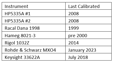
Only the MXO4 is in calibration, according to its spec we can expect: “0.2ppm (after cal), 1ppm (during cal interval)”.
The MXO4 can’t easily be coerced into measuring frequency with 8 digit precision (no shame there, it’s a scope). However, its built-in signal generator offers pretty much the same frequency accuracy so my test method was to set it to generate a 10MHz sine wave and compare the frequency with the OCXO board, using all the frequency meters.

Using the MXO4 as the standard the other instruments are amazingly good considering their lack of calibration (actually the HP5335A result doesn’t count because I’d fiddled with it beforehand !).
The Rigol is the star here, 7 years old and 0.03ppm drift. They cost £423 now, but I think mine was a lot less when I bought it.
All we have proved so far is that the oscillators basically work, and that I didn’t have anything good enough to get close to checking the expected stability which should be of the order of parts per billion per week.
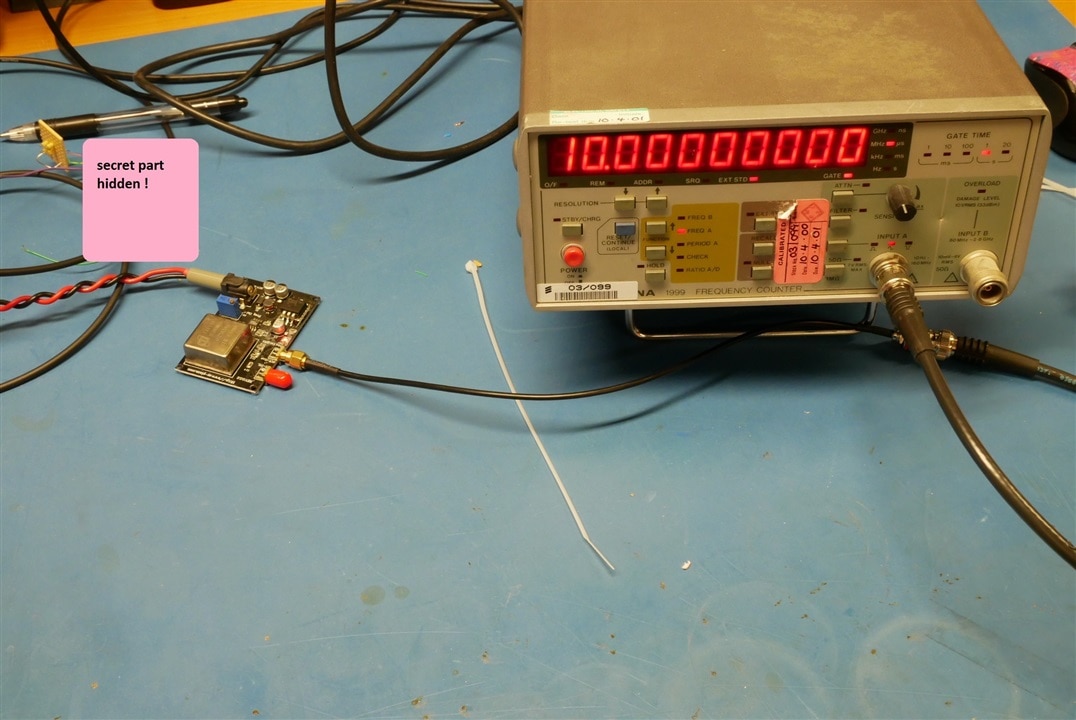
Of the instruments I have the Racal is the nearest to ideal for this work, with a resolution of 10 and bit digits. The stability of the oscillator isn’t good enough:
I needed something better and by far the cheapest way to get that is to use a GPS disciplined oscillator. I bought a Leo Bodnar Mini GPS Oscillator:
Over a couple of minutes (or more) this should be better than 1 part in 10E11 error which is better than I need.
This cost me a very reasonable £110 + VAT, but of course it wouldn’t work in the metal clad factory unit and I had to get Murray the Aerial man to fix the supplied antenna to the roof. It didn’t look very waterproof so I put it in a little plastic box. The lead it came with was just long enough to reach a suitable mounting point indoors.
I did some bench testing with the Racal 1999 meter and one of the OCXO boards.
The Racal can be remote controlled by GPIB (IEEE 488). A while ago I designed my own serial to GPIB board and built a few of them (this was a Covid Lockdown distraction activity). The oscillator project gave me a chance to use them for real. The first problem I had is that the Racal needs a 20 second gate time to hit its maximum resolution so it isn’t satisfactory to just issue a read command and wait 20 seconds for a reply. The solution to this is to use a serial poll to ask the Racal for its status and only try to read the result when its ready.
One of the advantages of designing your own interface boards is that you can write code to do whatever the ancient instruments want. One of the disadvantages is that you have to write code for anything you want to do – so I had to write the code for serial polling, which I hadn’t needed until now. It was easier than I expected once I had found the right IEE specification (IEEE Std 488.2-1992(R2004)).
I bought the Racal 1999 at an auction in 2002 or 3 (Can’t remember which) and one of its rear feet is missing. The temporary rubber replacement I had fitted had fallen off, so I decided to open it up to try and fix some new feet on it.
When I took the top cover off the back off the 1999, the GPIB interface board looked rather as if it had been attacked by an incontinent seagull. Splodged in sticky yellow and grey goo. As I set to cleaning this mess off with IPA, kitchen paper and a nylon brush I worked out what it was. Racal had obviously been worried that a good hard thump on the top or bottom panels might bend them so far that they shorted to the nearest pcb. This would obviously be a very bad thing: to prevent it they had stuck a few hemispherical grey rubber feet onto the pcb to act as emergency spacers. Unfortunately, some soft rubbery plastics seem to be subject to a strange liquification process over time (possibly catalysed by some metals). I’ve seen it before in old HP instruments where foam rubber pads have “melted” into corrosive goo.
There was no sign of overheating and only one of the rubber spacer feet had decomposed.
The bottom panel was protected in the same way but they had used one large square black stick on foot, it had “melted” too and was quite difficult to clean off completely.
I was so horrified by the mess on the lovely boards that I quite forgot to take any pictures !
Once the Racal 1999 was put back together I connected the mini-GPS frequency reference, set up for 10MHz output, to the Racal’s external frequency standard input.
I put the oscillator board in a little plastic box with a temperature sensor:
After running for a couple days I got this result.

This is quite good, no sign of any temperature effect and a pretty reasonable (although not outstanding) rate of drift.
I decided it was worth extending the experiment and needed to measure more than one oscillator at a time.
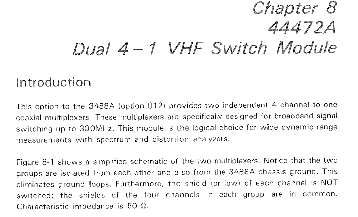
I have a collection of HP3488A Switch Control boxes. These are quite useful and have 5 slots for relay boards with different functions. For this experiment I used the VHF dual 4 multiplex plug in (HP44472A). These have 50R BNC connections and are good for 300MHz. (I wish I had more of them - they don’t often come up on Ebay).
Extract from the 3488A manual:
44472A plugged into a 3488A
I’ve set up the 3488A, the Racal 1999, a Keithley PSU and an fine 15 year old PC running Windows XP to control it all. In keeping with the period nature of the rest of the gear the control program is written in VB6 SP5.
It all ran for about 3 days before a short (few seconds) power dropout shut it down.
The data was processed in MATLAB which also drew the graphs.
Three days is enough data to start to draw the picture.
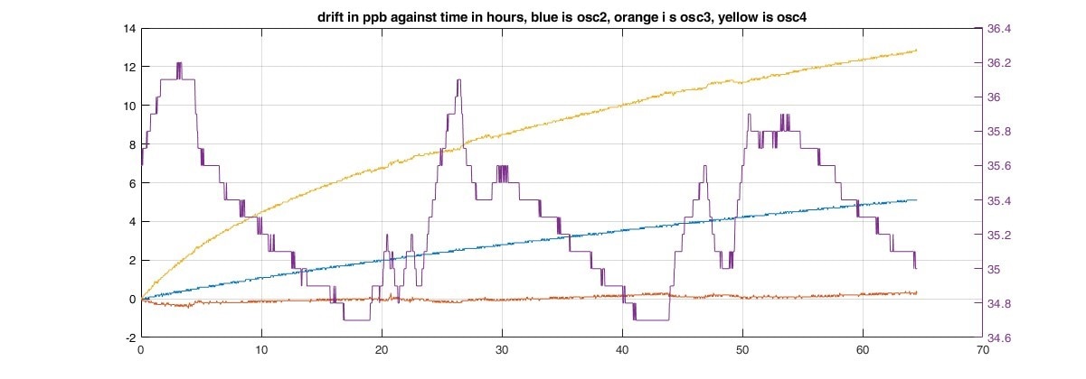
Osc3 is good enough to deserve a plot of its own:
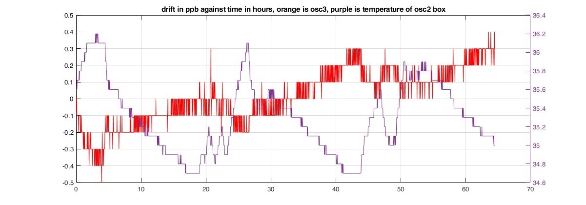
It’s managing about 0.5ppb in 65 hours = approx 2 parts in 1E10 per day (About 0.55 seconds per year.)
The temperature sensor is inside osc2’s enclosure and just gives a vague idea of the variation in ambient temperature in the lab. There isn’t really enough data to sort out the variation due to temperature changes but it looks like about 0.4ppb and the lab temperature changes by about 5C over 24 hours in the present weather conditions. This makes the temperature sensitivity about 0.1ppb per degree K which is not bad. The board is just lying on a bench in the lab.
The other two boards are about 10x and 20x worse.
Discoveries so far
These low cost oscillators can give quite good performance, but on the ready made boards there is a big variation between samples. Ranging from very good to OK. To properly assess the oscillators I need to out them on my own boards, made with parts of known good provenance and/or instrument the boards to check that there is no drift of power supply or refence voltage.
I thought that the results were good enough to buy 15 oscillators. These have been removed from equipment by band sawing the board so its up to me how much I abuse them by un-soldering. The oscillators without boards cost about £2.50 each.
Although the oscillators themselves are quite cheap you need a way of measuring them – and that implies a GPS locked time standard and a frequency meter with sufficient resolution. If you only want one it might be cheaper to buy it ready made.
The cheapest 10MHz OCXO in Farnell’s catalogue is a Bliley part offering ageing rates of 1ppb per day or 100ppb per year. It costs £58.
Step up to £177 and you get an IQD part offering 0.5ppb per day and 50ppb per year. The best of my three is better than that.
Future Experiments
First I’ll leave my three oscillators resting for a few days. Then I’ll power them up and run a24 hour test. And then leave them powered up for a week or more and test from time to time. This is all aimed at seeing how much they settle in.
Then I’ll add some instrumentation to the test rig to monitor supply voltage and the frequency tuning voltage. I’m suspicious that the frequency tuning arrangement on the boards may be less stable than the oscillators.
Finally I’ll design a board of my own with built in instrumentation, a 16 bit DAC with ultra stable precision voltage reference, and power supply regulation locked to the voltage reference.
If anyone wants more detail, please ask.
Comments welcome.
MK

-

shabaz
-
Cancel
-
Vote Up
0
Vote Down
-
-
Sign in to reply
-
More
-
Cancel
Comment-

shabaz
-
Cancel
-
Vote Up
0
Vote Down
-
-
Sign in to reply
-
More
-
Cancel
Children