


There are many types of synchros, Rx, Tx, and Resolvers. But what you have to remember that they are all just motors. As you can see this is really just a 3 phase motor, that is the three (3) Stators, are 120 degrees apart. But you ask what is the Rotor winding for? Well if 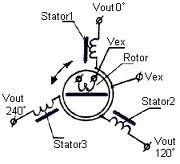 you look at the picture of your cars alternator with out the diodes it kind of does the same thing as the Drive winding on the alternator. So if you took the diodes out of the alternator, and you put a 400 Hz sine wave on the Drive winding, remember you have to spin it, you will get 400 Hz 3 phase power, just what I need for my plane.
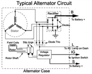
Duh Now What 
So now I have you all throughly confused. Right?
In a perfect synchro world you will have a Tx (like on a flap), and the Rx (in the cockpit) which is inside a indicator, both Rotors are driven in parrallel. So when the flap is moved, the changes on the 3 Stators windings are impressed from the Tx, to the Rx and if by magic the needle in the indicator moves with the flap.
I will not bore you with the math behind this, but this is a question?
What would happen if you put on the 3 Stators, a 400hz, 3 phase, that is each one of the phase are 120 degress apart, sine wave???
But wait, what about the rotor?? Ok that's the key. Remember what we did with that alternator? We do the same thing here. But we don't have to spin the syncrho, we spin it, or move it electrically!
| Digital Resolution of Angular Displacement | |||
|---|---|---|---|
| Bits | n2 | Degrees | BAM |
| 1 | 2 | 180 | 32768 |
| 2 | 4 | 90 | 16384 |
| 3 | 8 | 45 | 08192 |
| 4 | 16 | 22.5 | 04096 |
| 5 | 32 | 11.25 | 02048 |
| 6 | 64 | 5.625 | 01024 |
| 7 | 128 | 2.8125 | 00512 |
| 8 | 256 | 1.40625 | 00256 |
| 9 | 512 | 0.703125 | 00128 |
| 10 | 1024 | 0.3515625 | 00064 |
| 11 | 2048 | 0.17578125 | 00032 |
| 12 | 4096 | 0.087890625 | 00016 |
| 13 | 8192 | 0.043945312 | 00008 |
| 14 | 16348 | 0.021972656 | 00004 |
| 15 | 32768 | 0.010986328 | 00002 |
| 16 | 65536 | 00001 | |
Remember those 3 phases that you put on the Stators well if we call the unshifted signal the reference and you apply it also to the Rotor winding. Your indicator should point to 0. Ok so far?
Now if you phase shift the signal 90 degrees on the Rotor winding your indicator should move to 90 degrees.
Wow this is simple ***, right?
Lets get down to business. You can see a with your eyes about a ½ degree movement. Don't believe me look at your analog watch's second hand. 1 second is 1/60 of a circle. So you need about 1/10 of a degree so the indicator will float. So by checking the table you will see you only need 12 bits of resolution. I have also indicated a column for 16 bit BAM, as they are much easier to deal with, than degrees. And I don't have to use the Trig functions. To understand how to calculate the BAM please look at the link below. One more thing about a BAM it only represents part of a circle. I know I hear the question but we only need 12 bits so why use 16 and through away 4 bits? Well remember the is a computer and it likes things in 8 bit chunks, so getting a 16 bits on a 32 bit embedded CPU is no problem.
Here are two 16 bit functions, I wrote them as that you will need:
#define TO_BAMS16(x) (((x)/360.0) * 65536)
#define TO_DEGS16(b) (((b)/65536.0) * 360)
**you will notice that I wrote them as a #define and I let the preprossor take care of it, rather than making them a formal function, that way I can avoid the call and return time. You will also notice the 16 at the end of the name, as I also have 32 versions of the functions.The 16 bit version is fine for the instruments but with the 32 bit version, I can resolve down to a postage stamp size any where in the world!.
 Keep Tuned In More To Come
Cris H~
BTW:
- BAMS means a Binary Angular Measurement
- Synchro and Resolver Engineering Handbook
- Synchro / Resolver Conversion Handbook

