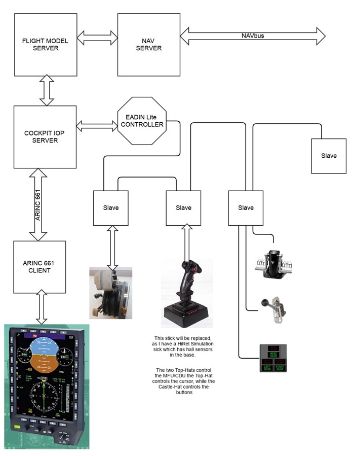
Well here is the other half of the roadmap! This concerns the integration between the:
- Flight Model Server and the NavServer.
- Cockpit IOP and the Flight Model Server.
- Cockpit IOP and ARINC-661 MFU/CDU
- Cockpit IOP and the EADEN Controllers
- EADEN to Slave CPU(s)
- I will describe the Throttle Quadrant, the Side-Stick, Gear Lever and Gear Lamps, and Rudder Pedals functions:
- Throttle Quadrant:
- Throttle Levers. (right and left)
- Throttle Gates and Finger Lifts. (right and left)
- The position of the Throttle Lever in the Gates is determined by 2 microswitches:
- OFF
- MAX THRUST.
- THRUST is the space between the two Gates, and its position is determined by a potentiometer.
- Flaps Lever (on the left side), and its position is determined by a potentiometer.
- Other Controls and Switches:
- Side-Stick:
- Inside the base, there is a Hall Sensor ring which determines the Pitch and Roll angles.
- Other Controls and Switches:
- Castel Hat Switch controls the selection of the MFD outer selector switches.
- Coolie Hat Switch controls the cursor on the MFD.
- Gear Lever and Lights
- Gear Lever itself has several functions:
- Gear UP/Down
- Gear Down for weight on wheels (this prevents retracting the gear when on the ground.
- Gear Lights
- RED / Gear UP
- GREEN / Gear Down and Locked
- AMBER Blinking Gear is in movement.
- Rudder Pedals with Toe Brakes:
- Controls the position of the Rudder. This uses one potentiometer.
- Force on the top of the Rudder Pedals controls the Wheel Brakes. This uses one potentiometer per side.
- Engine Start Panel
- Switches (Right and Left) only control the 2 small automotive engines that are in the fuselage.
- Run switches that select which mode the ignition is in.
- Stop
- Start
- ignition A
- ignition B
- Both
- LED displays that show the RPM (one per engine). 3 digits each.
- Start Switch which can crank ether engine. depending on Throttle Lever Position and of the engine RUN Switch in the Start. position.
- Gear Lever itself has several functions:
- Throttle Quadrant:
- When the Flight Model Server is started it is in the heartbeat mode which means it is just sending an empty frame only consisting of just the UNIX timestamp, 64bits.
- AT this time you can enter one of two modes:
- VFR
- IFR
- Assuming you are in IFR flight you would use the MFU/CDU to enter the Airport and known location. This information is transmitted to the Flight Model Server and the Nav Server
- Assuming you start the engines, when you advance the throttles the EADINLite Controller will send a message to the Cockpit IOP which in turns sends it Flight Model Server which again updates the NAVserver.
- Information entered into the MFU/CDU is an ARINC-661 system. This can put all manner of information on MFU/CDU. The buttons can be manually pushed and can also be controlled via the MFU/CDU Sidestick's Castel-Hat switch. The sidestick's Coolie-Hat controls the MFU/CDU Cursor, and the Red Button on the right is for the sidestick's enter command.