


Well here we are again back at the MPCD this seems like "The Neverending Story", oh well here goes. I had originally specified the MAX6955 LED display driver IC. A problem came up and it appeared to only support Charlieplexing, a technique to use fewer wires to drive your LEDs.
Background: Just to keep you all up to date I have included the links to the other blogs in this series: Hacking the Navigation Computer Display, Software Overview: Nav IOP.
New Analysis:  As I have previously stated that this display is a mixture of both 7 and 16 segment displays. These displays are in reality are very small incandescent lamps1. Now since I want all the bell and whistles, ie lamp test, blink any or all segments and dim them. I guess I will have to write this driver for my self. The segments are clockwise: a1, a2, b, c, d1, d2, e, f. Now the middle, right to left: g1, g2. Now the rest, clockwise: h, i, j, k, l, m.
Below I have constructed a table to show which segments are light for any letter.
| High Nibble | Low Nibble | 16 Segment Font Map | |||||||||||||||||
| ASCII | DATA | A1 | A2 | B | C | D1 | D2 | E | F | G1 | G2 | H | I | J | K | L | M | ||
| 30 | FF09 | 0 | 1 | 1 | 1 | 1 | 1 | 1 | 1 | 1 | 0 | 0 | 0 | 0 | 1 | 0 | 0 | 1 | 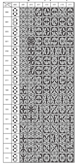 |
| 31 | 0300 | 1 | 0 | 0 | 1 | 1 | 0 | 0 | 0 | 0 | 0 | 0 | 0 | 0 | 0 | 0 | 0 | 0 | |
| 32 | EECO | 2 | 1 | 1 | 1 | 0 | 1 | 1 | 1 | 0 | 1 | 1 | 0 | 0 | 0 | 0 | 0 | 0 | |
| 33 | FC40 | 3 | 1 | 1 | 1 | 1 | 1 | 1 | 0 | 0 | 0 | 1 | 0 | 0 | 0 | 0 | 0 | 0 | |
| 34 | 31C0 | 4 | 0 | 0 | 1 | 1 | 0 | 0 | 0 | 1 | 1 | 1 | 0 | 0 | 0 | 0 | 0 | 0 | |
| 35 | CD84 | 5 | 1 | 1 | 0 | 0 | 1 | 1 | 0 | 1 | 1 | 0 | 0 | 0 | 0 | 1 | 0 | 0 | |
| 36 | DFCO | 6 | 1 | 1 | 0 | 1 | 1 | 1 | 1 | 1 | 1 | 1 | 0 | 0 | 0 | 0 | 0 | 0 | |
| 37 | F000 | 7 | 1 | 1 | 1 | 1 | 0 | 0 | 0 | 0 | 0 | 0 | 0 | 0 | 0 | 0 | 0 | 0 | |
| 38 | FFC0 | 8 | 1 | 1 | 1 | 1 | 1 | 1 | 1 | 1 | 1 | 1 | 0 | 0 | 0 | 0 | 0 | 0 | |
| 39 | FDC0 | 9 | 1 | 1 | 1 | 1 | 1 | 1 | 0 | 1 | 1 | 1 | 0 | 0 | 0 | 0 | 0 | 0 | |
| 45 | CFC0 | E | 1 | 1 | 0 | 0 | 1 | 1 | 1 | 1 | 1 | 1 | 0 | 0 | 0 | 0 | 0 | 0 | |
| 4E | 3324 | N | 0 | 0 | 1 | 1 | 0 | 0 | 1 | 1 | 0 | 0 | 1 | 0 | 0 | 1 | 0 | 0 | |
| 53 | DDC0 | S | 1 | 1 | 0 | 1 | 1 | 1 | 0 | 1 | 1 | 1 | 0 | 0 | 0 | 0 | 0 | 0 | |
| 57 | 3305 | W | 0 | 0 | 1 | 1 | 0 | 0 | 1 | 1 | 0 | 0 | 0 | 0 | 0 | 1 | 0 | 1 | |
| 80 | LT | 1 | 1 | 1 | 1 | 1 | 1 | 1 | 1 | 1 | 1 | 1 | 1 | 1 | 1 | 1 | 1 | ||
| 81 | CR | 0 | 0 | 0 | 0 | 1 | 1 | 0 | 0 | 0 | 0 | 0 | 0 | 0 | 0 | 0 | 0 | ||
| 20 | SP | 0 | 0 | 0 | 0 | 0 | 0 | 0 | 0 | 0 | 0 | 0 | 0 | 0 | 0 | 0 | 0 | ||
I will have to most likely to scrap the use of a hex to 7segment decoder and do it software as well.
Please note that the software below is not complete this is my rabid mined at 3 am. LOL And is far from being complete I still will have to rebuild the tables to add the Decimal Point(part of the display hardware), and dimming the display, this most likely will have to be a PWM signal generated from a local Arduino, etc. So this means I need 17 Select pins: 4 (hex lamps), 13 (7 seg lamps) plus the 25 Drive pins: (17 (hex)segs, 8 (7 seg) for a total of 42 pins. .
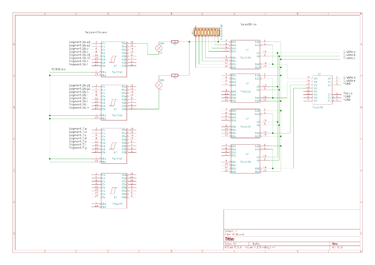
To implement a dimmer control I plan to use 4x SN74LS240NSN74LS240N an Octal Buffers with Tri-State outputs to the lamp segment I will then add a limiting resistor in series with the lamp segment to ground open collector output of a SN74LS156. The Arduino PCM output will drive the gate control pins 1 19 on the 4 SN74LS240NSN74LS240N via a buffer to deal with the fan-out load as each SN74LS240 is two loads(pins 1 19 x 4 8 Ouch. 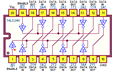
Drive and Select Circuit Explained. With the Arduino DigitalPins driving the 16 segments and 7 segments for a total of 23 segment drive pins. When the Select segments are turned on an (ie a a1 will be seen on all 4 16 segment displays simultaneously) then to provide a sink the correct display must be selected and be turned off allowing current tol flow through the limiting resistors, while the deselected will be turned on and blocking current flow. This scheme requires only 28 digital pins (plus decimal points).
| millicandelas | ||
| Outputmcd | volts | Ima |
|---|---|---|
| 44 | 4 | ~15 |
| 30 | 3.5 | ~14 |
More Changes: The following information was acquired over a phone call to Wamco today:
This is in the header files:
struct Display16Segs {
unsigned char Code;
int nibble[4]; }
struct Display16Segs displayHex[] = {
{{0x20}, {0x0, 0x0, 0x0, 0x0}},
{{0x30}, {0xF, 0xF, 0x1, 0x09}}, {{0x31}, {0x0, 0x3, 0x0, 0x0}}, {{0x32}, {0xE, 0xE, 0xC, 0xO}}, {{0x33}, {0xF, 0xC, 0x4, 0x0}}, {{0x34}, {0x3, 0x1, 0xC, 0x0}},
{{0x35}, {0xC, 0xD, 0x8, 0x4}}, {{0x36}, {0xD, 0xF, 0xC, 0x0}}, {{0x37}, {0xF, 0xF, 0x0, 0x0}}, {{0x38}, {0xF, 0xF, 0xC, 0x0}}, {{0x39}, {0xF, 0xD, 0xC, 0xO}},
{{0x45}, {0xC, 0xF, 0xC, 0x0}},
{{0x80}, {0xF, 0xF, 0xF, 0xF}}, {{0x81}, {0x0, 0xC, 0x0, 0x0}}};
int lookup16seg( unsigned char[2], int HL );
This is the function:
int lookup16Segs ( unsigned char* code, int HL ) {
int value; for ( int scan = 0; scan < 17; scan ++ ) {
if ( code == displayHex.code[ scan] ) {
if ( HL == 0 ) {
// return nibbles 1 & 2 (msb)
}
else {
// return nibbles 3 & 4 (lsb)
}}}
return value; }
* the 16 segment display font map and lamp images came from the MAX6955 datasheet.
Keep Tuned In, More To Come ~~Cris  |
Back to the Main Index |
|
REVISIONS:
|
Top Comments