


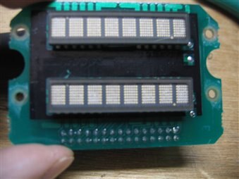
I have been fighting to get my dual display board to function. The first attempt was to use a 50-pin breakout board: FAIL; The second attempt was to pin the ICs to the connector which is an IDC male with a notch (upper-left 1, lower-left, etc. FAIL; Third and final attempt worked! I said the heck with their number scheme. So I went with an old standard row 1 upper-left pin 1 - 15; lower-right pin 16 - 30 which is now over pin 1.  So without further eloquence here is the 30 pin header interface listed by IC pin number:
| IC Pins | Upper Display | Lower Display | Color | Header Pin | Mega256 | IC Pins | Upper Display | Lower Display | Color | Header Pins | MEGA Pins | |
|---|---|---|---|---|---|---|---|---|---|---|---|---|
| 1 | CLS | GREEN | 9 | 22 | 32 | A4 | A4 | ORANGE | 17 | I2C.A4.25 | ||
| 1 | CLS | PURPLE | 23 | 50 | 31 | A3 | A3 | WHITE | 14 | I2C.A3.24 | ||
| 2 | CLK | ORANGE | 27 | 23 | 30 | A2 | A2 | BLUE. | 15 | I2C.A2.23 | ||
| 2 | CLK | YELLOW | 26 | 49 | 29 | A1 | A1 | GREEN | 13 | I2C.A1.22 | ||
| 3 | WR! | WR! | BROWN | 8 | 40 | 28 | A0 | A0 | YELLOW | 16 | I2C.A0.21 | |
| 4 | CE! | ORANGE | 6 | 24 | 27 | FL! | GREEN | 4 | 27 | |||
| 4 | CE! | BLUE | 24 | 48 | 27 | FL! | YELLOW | 5 | 45 | |||
| 5 | RST! | RED | 28 | 25 | No Pins 23 through 26 | |||||||
| 5 | RST! | BLUE | 3 | 47 | ||||||||
| 6 | RD! | GREEN | 25 | 26 | ||||||||
| 6 | RD! | RED | 7 | 46 | ||||||||
| No Pins 7 through 10 | ||||||||||||
| 11 | D0 | D0 | RED | 18 | I2C.B0.1 | 22 | D7 | D7 | GRAY | 22 | I2C.B7.8 | |
| 12 | D1 | D1 | GRAY | 12 | I2C.B1.2 | 21 | D6 | D6 | WHITE | 21 | I2C.B6.7 | |
| 13 | D2 | D2 | PURPLE | 11 | I2C.B2.3 | 20 | D5 | D5 | BLACK | 20 | I2C.B5.6 | |
| 14 | D3 | D3 | BROWN | 19 | I2C.B3.4 | 19 | D4 | D4 | BLUE | 10 | I2C.B4.5 | |
| 15 | na | na | 18 | GND | GND | BROWN | ||||||
| 16 | Vdd | Vdd | RED GRAY | 1 2 | 17 | GND | GND | BLACK | ||||
Notes:
| ||||||||||||
I will also use Arduino Mega pins 50, 49, 48, 47 53, 52, 51 for my two switches, using three-bit BCD code and pin 46 for the switch interrupt. I generate the interrupt by using a quad input or-gate Priority Encoder whose output EO goes to a Schmitt Trigger to actually signal for the interrupt. I got the 15 pins by 2 rows with Wire-Wrap tails from Samtec as samples.
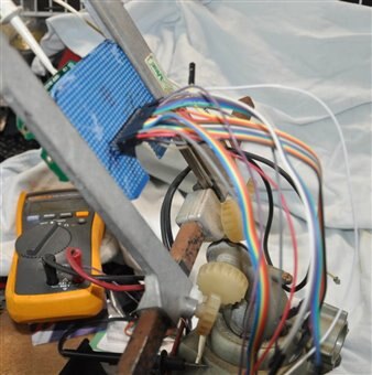
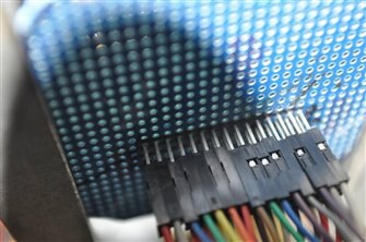
Below are a few snaps of the test harness. Without the PanaVice with the PCB holders, this was a daunting task as you have to work on both sides at the same time. I also tried my 3M/AP Products TC-48 which never made contact with the pins, as it was made for plastic or ceramic parts that have different geometries but still fit the normal pin spacing.
..
Top Comments