 |
| These three images are from "Embed With Elliot: Debounce Your Noisy Buttons" |
Why do I say aftermath? Well to put it simply it might have been a bit of an overreach. I spent more than a few days trying in vain to get the display board pins identified. So here are some videos for the Fuel Load Indicator. First up are the function switches.

 |
 |
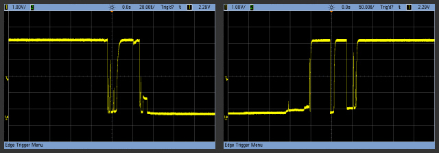
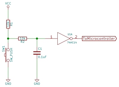
| BEFORE | RC Circuit |
|
There is one more board and that is the Signal Conditioner. This is a small board that connects to the switches and the Interface board. The Signal Conditioner is a simple RC network where, T = C * R, or .001 seconds, to get rid of the jitter or ringing. I am using interrupts from the switches provided by an SN74LS147 which is a 7-inputs to BCD outputs that triggers the interrupt. To get the 3-bit outputs (Arduino inputs) into one integer I used the bit shifting:
The displays IC are a pair of DSP-2131TXV, which are smart devices that is intended to have both an Address-bus and Data-bus that the Arduino does not have. The problem is solved by using an I2C I/O 16-bit expander. The MCP 23017 can be used as two separate 8-bit registers, which become my two buses. One of the problems that I have is that the Display Board is bolted into the housing. At which point the Interface board plugs into the Display board. The problem is getting them apart (it's a pain). You have to unmount the Display board from the housing. So that means I have to trim the Interface board so that I can get to the four screws in the bottom of the housing.
AFTERTHOUGHTS: Having problems with Arduino's CAN implementation. I have decided to sort of roll my own interface based loosely on CANopen which is a superset of CAN and very closely related to CANaerospace itself. But for testing USB will work fine. I have a crude program on my PC which can send and receive frames. CANopen-Slave on git |
Now here is some WireWrap on the custom interface board.
Componentes on the Interface board.

Top Comments