element14 Community
element14 Community
    Register Log In
  • Site
  • Search
  • Log In Register
  • Community Hub
    Community Hub
    • What's New on element14
    • Feedback and Support
    • Benefits of Membership
    • Personal Blogs
    • Members Area
    • Achievement Levels
  • Learn
    Learn
    • Ask an Expert
    • eBooks
    • element14 presents
    • Learning Center
    • Tech Spotlight
    • STEM Academy
    • Webinars, Training and Events
    • Learning Groups
  • Technologies
    Technologies
    • 3D Printing
    • FPGA
    • Industrial Automation
    • Internet of Things
    • Power & Energy
    • Sensors
    • Technology Groups
  • Challenges & Projects
    Challenges & Projects
    • Design Challenges
    • element14 presents Projects
    • Project14
    • Arduino Projects
    • Raspberry Pi Projects
    • Project Groups
  • Products
    Products
    • Arduino
    • Avnet & Tria Boards Community
    • Dev Tools
    • Manufacturers
    • Multicomp Pro
    • Product Groups
    • Raspberry Pi
    • RoadTests & Reviews
  • About Us
  • Store
    Store
    • Visit Your Store
    • Choose another store...
      • Europe
      •  Austria (German)
      •  Belgium (Dutch, French)
      •  Bulgaria (Bulgarian)
      •  Czech Republic (Czech)
      •  Denmark (Danish)
      •  Estonia (Estonian)
      •  Finland (Finnish)
      •  France (French)
      •  Germany (German)
      •  Hungary (Hungarian)
      •  Ireland
      •  Israel
      •  Italy (Italian)
      •  Latvia (Latvian)
      •  
      •  Lithuania (Lithuanian)
      •  Netherlands (Dutch)
      •  Norway (Norwegian)
      •  Poland (Polish)
      •  Portugal (Portuguese)
      •  Romania (Romanian)
      •  Russia (Russian)
      •  Slovakia (Slovak)
      •  Slovenia (Slovenian)
      •  Spain (Spanish)
      •  Sweden (Swedish)
      •  Switzerland(German, French)
      •  Turkey (Turkish)
      •  United Kingdom
      • Asia Pacific
      •  Australia
      •  China
      •  Hong Kong
      •  India
      •  Korea (Korean)
      •  Malaysia
      •  New Zealand
      •  Philippines
      •  Singapore
      •  Taiwan
      •  Thailand (Thai)
      • Americas
      •  Brazil (Portuguese)
      •  Canada
      •  Mexico (Spanish)
      •  United States
      Can't find the country/region you're looking for? Visit our export site or find a local distributor.
  • Translate
  • Profile
  • Settings
Personal Blogs
  • Community Hub
  • More
Personal Blogs
NexGen Flight Simuator NexGen: Fuel Load Indicator iv.a Making a new major PCB
  • Blog
  • Documents
  • Mentions
  • Sub-Groups
  • Tags
  • More
  • Cancel
  • New
  • Share
  • More
  • Cancel
Group Actions
  • Group RSS
  • More
  • Cancel
Engagement
  • Author Author: phoenixcomm
  • Date Created: 2 Sep 2019 2:05 AM Date Created
  • Views 241 views
  • Likes 4 likes
  • Comments 0 comments
  • diy cockpit
  • hdsp-2131
  • pcb
  • iss 9d-00653-1
  • arduino mega pro
  • hdsp-2111
  • parker 219-100-001
  • fuel load indicator
  • flight simulation
  • arduino
  • nexgen flight simulator
  • software
Related
Recommended

NexGen: Fuel Load Indicator iv.a Making a new major PCB

phoenixcomm
phoenixcomm
2 Sep 2019

Well, really need to finish something around here so I will take up where we left off with the fuel load indicator, in parts 1, 2 and 3. And I can't go on without a PC board so I decided to make one this evening. First I need a piece of Vector Board to lay the board on.  The problem lies in the fact that that I don't have any way to get reliable dimensional info and then the 18 pins on the board that connects to the display saying that that means that the two boards have to line up. That is the display board and the new control board that I will have to build. Please keep in mind that both the old Power Supply and Controller boards are headed to the scrap pile for gold reclamation. I cut the part out with a hack saw first lubed with a little WD-40, as the blue board was FR-4 ie fiberglass. To get the final shape I will use my Dremel with an abrasive disk.imageimage

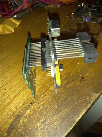
The steps I took were not pretty and I will get some boo's (I know this).

  1. Cut back the shroud on the connector without destroying the connector.  image  (you can see the hatchet job on the right)
  2. Insert the 18 pins through the Vector board.
  3. Draw the outline of the Display board with the pins in.
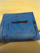
  4. Draw the outline of one of the other boards on top of the outline in step 3
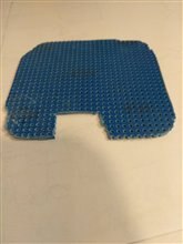
  5. Cut Vector board about 1/4" larger all the way around.
  6. Sand to fit. image
  7. It fits but it sucks.

Oh well, I will have to get a 2D scan and then cut them on a CNC Laser or a CNC Router.

Since I Wire Wrap I will mount the components on the bottom of the board with the legs pointing up. This board will hold the TI CAN IO expander

and a second card will be mounted on the top of the first with stand-offs, with the legs pointed down. This board will hold the Arduino, and support chips.

This should be a self-contained slave with the RS485/RJ45 jacks. I don't know I will have to make a PCB as the Mega 256 is a surface mount part.


imageimageimage
Steps 2 - 4Step 6Step 7
  • Sign in to reply
element14 Community

element14 is the first online community specifically for engineers. Connect with your peers and get expert answers to your questions.

  • Members
  • Learn
  • Technologies
  • Challenges & Projects
  • Products
  • Store
  • About Us
  • Feedback & Support
  • FAQs
  • Terms of Use
  • Privacy Policy
  • Legal and Copyright Notices
  • Sitemap
  • Cookies

An Avnet Company © 2025 Premier Farnell Limited. All Rights Reserved.

Premier Farnell Ltd, registered in England and Wales (no 00876412), registered office: Farnell House, Forge Lane, Leeds LS12 2NE.

ICP 备案号 10220084.

Follow element14

  • X
  • Facebook
  • linkedin
  • YouTube