


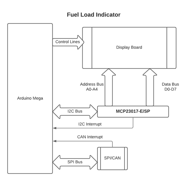
 Well, here we are back again, with the Fuel Load Meter. This thing has given me nothing but grief. So I am going to take another whack at it. I still have to make sure that the wiring is correct. and then write the code. The problem I was/am having is the 30-pin connector that goes to the display. This is a Never-Ending Story not to be confused with the movie of the same name (German: Die Unendliche Geschichte). It seems like you take one step forward and two or three backward. This time around I hope to get it right. I need a better plan of attack. Below is the block diagram.
- I have to fix the mangled connector on the display board. I have a bad habit of putting things on the floor or they just fall off my desk into The Abyss, a movie (1989) of the same name.
- I have to double-check my wiring.
- I have to power up the Arduino and Display Board combo. but the Display Board will be under its own power. Only the grounds will be connected to support logic levels.
- Re-wite code that I found on-line.
- Run a self-test. ie walking characters and all dots on + blink. One display at a time. Then it prints on the upper display BITE Test. On the lower line print tank number OK, then System Functional. (and turns on interrupts)
- Build a small input board for the switches. As there are 2 x SPDT Switches that means you have 5 combinations. But we really need 4 as we don't care about zero cases. This board has a 7:3 BCD priority encoder and a Schmitt Trigger. The output of the encoder will be bit shifted to pack the number. And the encoder has an auxiliary output that follows key states, and this is what will trigger the interrupt.
- Maybe get the AeroCAN lib working??

