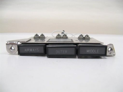
 This is a ubiquitous panel indicator the images are for the unit used on a 1973 Cessna 421. My indicator was used in the military as instead of "AIRWAYS" it says "INNER" which is a VHF radio beacon and is part of the ILS, Instrument Landing System. This annunciator is part of my RSS, Radio SubSystem. This annunciator informs the pilot, where the aircraft is in relationship to the runway. The three indicators are as follows: The outer marker, which normally identifies the final approach about 1 NM before you intercept the glide slope. The middle marker is positioned 0.5 to 0.8 NM before the runway threshold. An inner marker is located at the threshold, or the beginning of the runway.
 As you can see there isn't much to the Annuctiator. Please note there is a contact missing from one of the covers. The two arms slide into slots on the side of the covers. For retention, there is a small slot in the cover at the rear of the unit.
CANaerospace does not specifically designate node-id for the marker lights, but it states that VOR/ILS radio frequencies(4) are 1104 - 1107. So I might need a reserved address, 1300 -1499, one per radio. Normally the receivers have marker lamp outputs, which go to the lamps.
For wiring the lamps, two connections per lamp and four connections per device. which means that the top two contacts are pins 1 and 2 while the lower pins are 3 and 4. which means that:
the signal is on pin 1 and pin 2 while the return is on pins 3 and 4. So. the harness will have four wires Outer, Middle, and Inner plus a return line. since they are 28v I will be using 4Nxx optoisolators for galvanic isolation and a transistor to boost the current, so I need since each type 327 lamp is rated at 1 w with a voltage of 28v yields 35.714 mA I need 2 bulbs so I need CollectorI of better than 75ma. with a CEV of 50V or better.
