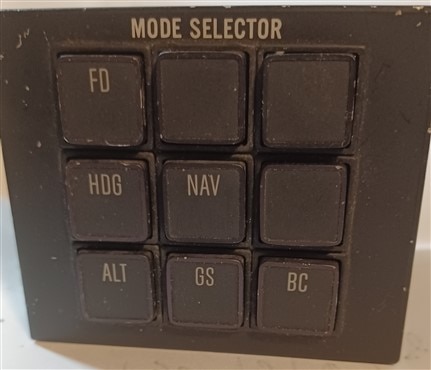
 I have had this Mode Selector for more than a few years so I guess, "The time has come,' the Walrus said, To talk of many things:
-The Walrus and the Carpenter BY LEWIS CARROLL
 This one should be straightforward, on my Arduino Mega I will 2 x Schmitt Triggers, plus the RC filters, I will most likely route the 7 Schmitt Triggers from the switches into an MCP2017 and a Resistor array for pull-ups. Now for the outputs, I need 18 output lines, so that's 1 MCP2017 plus I will need to steal 2 more from the other MCP2017 - Easy Peasy - Lemon Squeezy
Each lamp type 727, which are rated 5v at 0.012A or about 12ma each, but each legend takes two of the lamps which is 0.024W, but the MCP2017 spec is"Maximum output current sourced by any output pin ....25 mA", or 0.025A. So I think I might need a small transistor to give me a little more current. As this is getting more convoluted by the second I will be forced to go with a PCB  The interface cables need 18 (lamp drive) +7 (inputs) =25 pins plus a 4-pin connector for 5 VDC (raw) for the lamps, p5 from the Arduino for the logic, and of course ground. and the RJ-45s for the CAN bus. CAN outputs are from an SPI module with an MCP215 controller with a TJA1050 transceive
| Connections | ||||
| L A M P S |
1 | |||
| 2 | ||||
| 3 | COM | N.O. | N.C. | |
| 4 | ||||
| 5 | ||||
To put the lamp wiring in perspective, pins 1 through 5, connect to two circuits, pins 2, and 4 run the top legend while pins 1, and 3 run the bottom legend.
| FD ENG |
AP GA |
VOR LOC |
| HDC ENG |
NAV ARM ENG |
NAV1 NAV2 |
| ALT ENG |
GS ARM ENG |
BC ON |
Arduino Interrupts:
SVC1 CAN bus interrupt (this tells the Arduino that the CAN module has data 1300
SVC2 CAN bus Lamps -- 1301
SVC4 Arduino -- 1302 (this tells the Arduino that the Mode Control Switches were pressed)
CANaerospace Info:
*CANid and Data Types are subject to change
DATA TYPE:
1301 ::= 4 Bytes but only the first 3 are used.
1302 ::= 4 Bytes but only the first 2 are used.
CANids: 1301, 1302, and where 1300 is the system itself.
LAMP Message Data (3 Bytes) Byte 3 has the switch address, and Byte 4 is the upper or lower lamps Byte 3 is the state ::= 0 (off) or 1 (on)
SWITCH Message Data (2 Bytes) Byte 3 has the switch address, and Byte 3 is the state ::= 0 (off) or 1 (on)
| ID | Byte 4 | Byte 5 | Byte 6 | Byte 7 |
| 1300 | Error Code (0-FFxHex) |
Defined As: | ||
| 1301* | 0-9 | 0-1 (0 upper), (1 lower) | 0-1 (0 off), (1 on) | |
| 1302* | 0-7 | 0-1 (0 off), (1 on) | ||
