


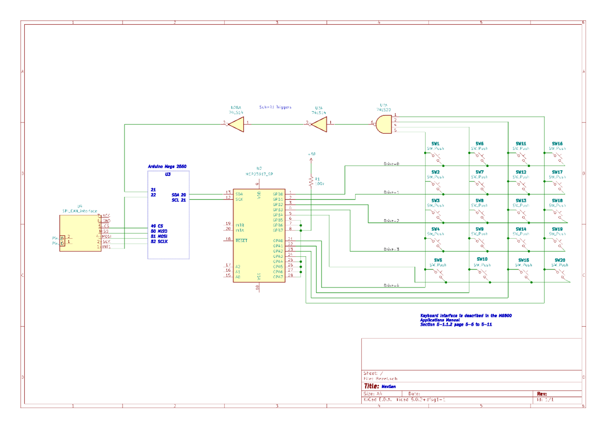
I have been down this road before but now I have the final solution. I found it in my old Motorola M6800 Applications Handbook, section 5-1.1.2 NonEncoded Keyboards. It used a PIA or Peripheral Interface Adapter, but since I am using an Arduino I need a part that will do the same thing. So I will replace the PIA with an MCP23017 16-bit I/O expander. As you can see I drive the data lines Data-0, and 4 with a high. When there is no key closure nothing happens but if a key is pressed 1) the active line is seen on its corresponding sense data lines Sense-0, 4 and there will be a signal change on the interrupt line. Switch definitions are as follows: TOP SW1 - 5, RSide SW6 - 10, Bottom: SW11 - 15, and LSide: SW16 - 20;
 |
|
** note I have to vet this code?! int keyLookup () {
if ( i = HIGH ) {
if ( j == HIGH ) { return ( MCP[i][j][0] ); }}}
|
Let me walk you through this.
- GPB will be the output and a one written into GPB0, 1, 2, 3, 4
- BPA0, 1, 2, 3, and 4 are inputs.
- interrupts are enabled
- On a key press, the high from the row is now on the associated column
- The NOR gate will change states
- use a for loop to scan the column for the hi
- disable the interrupts
- use a for loop to scan the row for the high while only looking at the column from above
- You should have the row and column.
- Since the column and row are now known we can do a lookup for the code to output
- GPB will be the output and a one written into GB0, 1, 2, 3
- //start over
- interrupts are enabled.
- // rinse and repeated
|
bezel.h volatile int row; #canNode 1 #define NodeID 82 #define ISR21 21 #define ISR22 22 struct mcp23017{ int io[5][5][1] = { { 0, 0, 1 }, { 0, 1, 2 }, { 0, 2, 3 }, { 0, 3 , 4},{ 0, 4, 5 }, { 1, 0, 6 }, { 1, 1, 7 }, { 1, 2, 8 }, {1, 3, 9 }, {1, 4 10 }, { 2, 0, 11 }, { 2, 1, 12 }, { 2, 2, 13 }, {2, 3, 14 }, {2, 4, 15 }, { 3, 0, 16 }, { 3, 1, 17 }, { 3, 2, 18 }, {3, 3, 19 }, {3, 4, 20 }; }
typedef struct mcp23017 MCP;
// CANbus #define STANDARD_CAN_11BIT 1
#define can_tx 2 // tx D2 #define can_rx 3 // rx D3
void loop() { //null } |
keys.h // top left & //counter-clockwise #define SW1 1 |
#include keys.h #include bezel.h
void setup () { // Can assignments #if STANDARD_CAN_11BIT #define CAN_ID_PID 0x7DF #else #define CAN_ID_PID 0x18db33f1 #endif
//MCP23017 mcp.begin(); // Assign pins MCP23017 int pin; // for MCP23017
for( pin = 0; pin < 16; pin++ ) { if( pin < 5 ) { pinMode(pin, OUTPUT);} else if( pin > 8 & pin < 13 ) pinMode(13, INPUT); else; Wire.beginTransmission(0x20); Wire.write(0x00); // IODIRA register Wire.write(0x00); // set all of port A to outputs Wire.endTransmission();
Wire.beginTransmission(0x20); Wire.write(0x01); // IODIRB register Wire.write(0x00); // set all of port B to outputs Wire.endTransmission();
} |
|
void ISR21 () { int col; for ( col = 0; col < 5; col++) { if( mcp.digitalRead( col ) == HIGH { column = col; }} |
void ISR22 () {
// is this heartbeat? disable ISR22; heartbeat( NodeID ); enable ISR22 } |
heartbeat (int nodeID ){ tx message node status } |
Note: the part where this uses CANaerospace has been DEPRECATED as I am now using an Ethernet Shield for communications. Please see Part iii - CAH March 21, 2023

