element14 Community
element14 Community
    Register Log In
  • Site
  • Search
  • Log In Register
  • Community Hub
    Community Hub
    • What's New on element14
    • Feedback and Support
    • Benefits of Membership
    • Personal Blogs
    • Members Area
    • Achievement Levels
  • Learn
    Learn
    • Ask an Expert
    • eBooks
    • element14 presents
    • Learning Center
    • Tech Spotlight
    • STEM Academy
    • Webinars, Training and Events
    • Learning Groups
  • Technologies
    Technologies
    • 3D Printing
    • FPGA
    • Industrial Automation
    • Internet of Things
    • Power & Energy
    • Sensors
    • Technology Groups
  • Challenges & Projects
    Challenges & Projects
    • Design Challenges
    • element14 presents Projects
    • Project14
    • Arduino Projects
    • Raspberry Pi Projects
    • Project Groups
  • Products
    Products
    • Arduino
    • Avnet & Tria Boards Community
    • Dev Tools
    • Manufacturers
    • Multicomp Pro
    • Product Groups
    • Raspberry Pi
    • RoadTests & Reviews
  • About Us
  • Store
    Store
    • Visit Your Store
    • Choose another store...
      • Europe
      •  Austria (German)
      •  Belgium (Dutch, French)
      •  Bulgaria (Bulgarian)
      •  Czech Republic (Czech)
      •  Denmark (Danish)
      •  Estonia (Estonian)
      •  Finland (Finnish)
      •  France (French)
      •  Germany (German)
      •  Hungary (Hungarian)
      •  Ireland
      •  Israel
      •  Italy (Italian)
      •  Latvia (Latvian)
      •  
      •  Lithuania (Lithuanian)
      •  Netherlands (Dutch)
      •  Norway (Norwegian)
      •  Poland (Polish)
      •  Portugal (Portuguese)
      •  Romania (Romanian)
      •  Russia (Russian)
      •  Slovakia (Slovak)
      •  Slovenia (Slovenian)
      •  Spain (Spanish)
      •  Sweden (Swedish)
      •  Switzerland(German, French)
      •  Turkey (Turkish)
      •  United Kingdom
      • Asia Pacific
      •  Australia
      •  China
      •  Hong Kong
      •  India
      • Japan
      •  Korea (Korean)
      •  Malaysia
      •  New Zealand
      •  Philippines
      •  Singapore
      •  Taiwan
      •  Thailand (Thai)
      • Vietnam
      • Americas
      •  Brazil (Portuguese)
      •  Canada
      •  Mexico (Spanish)
      •  United States
      Can't find the country/region you're looking for? Visit our export site or find a local distributor.
  • Translate
  • Profile
  • Settings
Personal Blogs
  • Community Hub
  • More
Personal Blogs
NexGen Flight Simuator NexGen: Multi-Purpose Color Display (F/A-18C/D MPCD): Hardware / Software Interface (switches)
  • Blog
  • Documents
  • Mentions
  • Sub-Groups
  • Tags
  • More
  • Cancel
  • New
  • Share
  • More
  • Cancel
Group Actions
  • Group RSS
  • More
  • Cancel
Engagement
  • Author Author: phoenixcomm
  • Date Created: 16 Aug 2015 5:28 AM Date Created
  • Views 508 views
  • Likes 4 likes
  • Comments 1 comment
  • nexgen
  • c
  • hardware
  • f-18
  • mpcd
  • arduino
  • diy_cockpit
  • software
Related
Recommended

NexGen: Multi-Purpose Color Display (F/A-18C/D MPCD): Hardware / Software Interface (switches)

phoenixcomm
phoenixcomm
16 Aug 2015
image

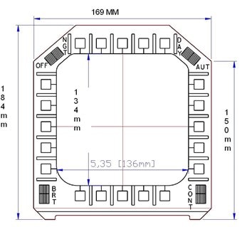
MPCD Prototype

Figure 1

Well, here we are back at the MPCD, I have blogged twice before about this unit. First, where I got the pin-out for  MPCD and got it working. Then I had to rewire the cable. Well, now it's the third time..


The Interface ( switches ) are arranged in 5 x 5 matrix, so I could just build a matrix, add diodes, and write a scan module. Nah, that's too much work! If you remember my CP-1252/ASN-128 CDU (Figure 2).  I interfaced the CDU  with an Arduino and the PS/2 interface. Good, this will simplify both my hardware development and software, REUSE the PS2 Keyboard code base. This gives me my code-base for both the CDU and the IOP.


The Set Up. Dah rules, there are just a few:

  • Each key switch is connected to the PS2 Keyboard controller an SPST, normally off, momentary push, non-locking switch.
  • Each key switch shall be referenced by its position on the bezel.
  • Each key switch shall be labeled in the code base as KeySwitch.[letter] ie the  busted switch on the bottom as KeySwitch.Q
  • Each key switch shall be lit by an internal LED.
  • Each LED shall be known as KeySwitchLED[letter] the same switch as before would now be KeySwitchLED.Q
  • For reference, all the switches and LEDs shall have two (2) contacts each. My notation ::= is defined as
    • Switch Common ::=  1
    • Switch Active Leg ::=  2
    • LED common ::= 3
    • LED anode ::= 4

Since there are 20 keys, I only need to use three eight-bit, I2C, I/O expanders, the Texas Instruments PCF8574A.Now that means I have 4 extra pins on expander #3. I have a chart (Figure 3) consisting of ASCII output, expander, i/o pin. It is color codedto help keep it straight.

RIGHT

LEFT (top down)RIGHT (top down)TOP (left to rightBOTTOM (left to right)
A.1.POF.1.P5K.2.P2P.2.P7
B.1.P1G.1.P6L.2.P3Q.3.P0
C.1.P2H.1.P7M.2.P4R.3.P1
D.1.P3I.2.P0N.2.P5S.3.P2
E.1.P4J.2.P1O.2.P6T.3.P3
ADDENDUM: It seems that the switches are labeled counter-clockwise from the top-left.

Interface Table
Figure 3

TOP ROW

LEFT TO RIGHT

LEFT ROW

BOTTOM UP

BOTOM ROW

RIGHT TO LEFT

RIGHT ROW

TOP DOWN

S20.IC3.D
LED20.IC.D
S15.IC2.G
LED15.IC5.G
S10.IC2.B
LED10.IC5.B
S1.IC1.A
LED1.IC4.A
S19.IC3.C
LED19.IC.C
S14.IC2.F
LED14.IC5.F
S9.IC2.A
LED9.IC5.A
S2.IC1.B
LED2.IC4.B
S18.IC3.B
LED17.IC6.B
S13.IC2.E
LED13.IC.5.E
S8.IC1.H
LED8.IC4.H
S3.IC1.C
LED3.IC4.C
S17.IC3.A
LED17.IC6.A
S12.IC2.D
LED12.IC5.D
S7.IC1.G
LED7.IC4.G
S4.IC1.D
LED4.IC4.D
S16.IC2.H
LED16.IC5.H
S11.IC2.C
LED11.IC5.C
S6.IC1.F
LED6.IC4.F
S5.IC1.E
LED5.IC4.E
cp-1252.jpg?w=300&h=254

CP-1252/ASN-128 CDU

Figure 2


The Communication. You should remember that I consider the Arduino rather stupid. So his function in life is to pass key presses to an IOP. The IOP has to generate the appropriate video and light the appropriate keys. So I want to make this device independent.  So let's get on with the Key LED processing.


First let's write the function "MFD_LED"  it will have two arguments: led_ID (char), Led_State (int)

and then the "LedDriver" it will have three arguments: expander_ID (int), Port_Number (int), led_state (int)


// 8574A address range 0x38 to 0x4F
// defines
#define EXPANDER1 0x38
#define EXPANDER2 0x39
#define EXPANDER3 0x3A
#define EXPANDER4 0x3C 
#define EXPANDER5 0x3E
#define EXPANDER6 0x41


image
Current Style Bezel
Figure 4
// prototypes

LedDriver( int expander_ID, int PortNumber, int led_state );
void MFD_LED( char led_ID , int led_state );  // the void might be changed to an int.
// Control the LEDs.
MFD_LED( char led_ID , int led_state ){
if(led_state => A && led_state <= H){
  LedDriver( EXPANDER4, PortNumber, led_state );}
if(led_state => I && led_state <= P){
  LedDriver( EXPANDER5, PortNumber, led_state);}
if(led_state => Q && led_state <= T){
  LedDriver( EXPANDER6, PortNumber, led_state );}
if(led_state > T){
    // error or special.}


LedDriver( int expander_ID, int Port_Number, int led_state ){
// This function is to wrap the 3 Arduino's Wire Libary calls.
Wire.beginTransmission(expander_ID);  //Begin the transmission to PCF8574A
Wire.send(led_state);                //Send the data to PCF8574A
Wire.endTransmission();              //End the Transmission
}


SOFTWARE: In fact, I will be using three (3) different software libraries:

  1. Ps2 Keyboard library that just outputs ASCII characters (no IBM scan codes).
  2. Wire library that talks to the PCF8574A I/O Expanders. 3 output for the LEDs and one input for some switches.
  3. Serial library that lets the Arduino communicate with the world via a USB virtual serial connection.


Stay Tuned In, More To Come,

~~Cris image


  • Sign in to reply
  • DAB
    DAB over 10 years ago

    Good post.


    It brings back a lot of memories about the initial glass cockpit efforts in the 1980's.


    DAB

    • Cancel
    • Vote Up 0 Vote Down
    • Sign in to reply
    • More
    • Cancel
element14 Community

element14 is the first online community specifically for engineers. Connect with your peers and get expert answers to your questions.

  • Members
  • Learn
  • Technologies
  • Challenges & Projects
  • Products
  • Store
  • About Us
  • Feedback & Support
  • FAQs
  • Terms of Use
  • Privacy Policy
  • Legal and Copyright Notices
  • Sitemap
  • Cookies

An Avnet Company © 2026 Premier Farnell Limited. All Rights Reserved.

Premier Farnell Ltd, registered in England and Wales (no 00876412), registered office: Farnell House, Forge Lane, Leeds LS12 2NE.

ICP 备案号 10220084.

Follow element14

  • X
  • Facebook
  • linkedin
  • YouTube