element14 Community
element14 Community
    Register Log In
  • Site
  • Search
  • Log In Register
  • Community Hub
    Community Hub
    • What's New on element14
    • Feedback and Support
    • Benefits of Membership
    • Personal Blogs
    • Members Area
    • Achievement Levels
  • Learn
    Learn
    • Ask an Expert
    • eBooks
    • element14 presents
    • Learning Center
    • Tech Spotlight
    • STEM Academy
    • Webinars, Training and Events
    • Learning Groups
  • Technologies
    Technologies
    • 3D Printing
    • FPGA
    • Industrial Automation
    • Internet of Things
    • Power & Energy
    • Sensors
    • Technology Groups
  • Challenges & Projects
    Challenges & Projects
    • Design Challenges
    • element14 presents Projects
    • Project14
    • Arduino Projects
    • Raspberry Pi Projects
    • Project Groups
  • Products
    Products
    • Arduino
    • Avnet Boards Community
    • Dev Tools
    • Manufacturers
    • Multicomp Pro
    • Product Groups
    • Raspberry Pi
    • RoadTests & Reviews
  • Store
    Store
    • Visit Your Store
    • Choose another store...
      • Europe
      •  Austria (German)
      •  Belgium (Dutch, French)
      •  Bulgaria (Bulgarian)
      •  Czech Republic (Czech)
      •  Denmark (Danish)
      •  Estonia (Estonian)
      •  Finland (Finnish)
      •  France (French)
      •  Germany (German)
      •  Hungary (Hungarian)
      •  Ireland
      •  Israel
      •  Italy (Italian)
      •  Latvia (Latvian)
      •  
      •  Lithuania (Lithuanian)
      •  Netherlands (Dutch)
      •  Norway (Norwegian)
      •  Poland (Polish)
      •  Portugal (Portuguese)
      •  Romania (Romanian)
      •  Russia (Russian)
      •  Slovakia (Slovak)
      •  Slovenia (Slovenian)
      •  Spain (Spanish)
      •  Sweden (Swedish)
      •  Switzerland(German, French)
      •  Turkey (Turkish)
      •  United Kingdom
      • Asia Pacific
      •  Australia
      •  China
      •  Hong Kong
      •  India
      •  Korea (Korean)
      •  Malaysia
      •  New Zealand
      •  Philippines
      •  Singapore
      •  Taiwan
      •  Thailand (Thai)
      • Americas
      •  Brazil (Portuguese)
      •  Canada
      •  Mexico (Spanish)
      •  United States
      Can't find the country/region you're looking for? Visit our export site or find a local distributor.
  • Translate
  • Profile
  • Settings
Personal Blogs
  • Community Hub
  • More
Personal Blogs
NexGen Flight Simuator NexGen Sim: ATR Box Universal Design.
  • Blog
  • Documents
  • Mentions
  • Sub-Groups
  • Tags
  • More
  • Cancel
  • New
  • Share
  • More
  • Cancel
Group Actions
  • Group RSS
  • More
  • Cancel
Engagement
  • Author Author: phoenixcomm
  • Date Created: 18 Jun 2018 6:00 AM Date Created
  • Views 434 views
  • Likes 3 likes
  • Comments 1 comment
  • nexgen
  • gimp
  • diy cockpit
  • atr box
  • image magic
  • kicad eda
  • nexgen flight simulator
  • baseboard design
Related
Recommended

NexGen Sim: ATR Box Universal Design.

phoenixcomm
phoenixcomm
18 Jun 2018

Ok well here is my Universal ATR box known as

Fullscreen contentimage_134590.html Download
<html><head><title>Jive SBS</title></head>
<body><font face="arial,helvetica,sans-serif">
<b>Error</b><br><font size="-1">
An general error occurred while processing your request.
</font></font></body></html>
ATR.poly. This design covers both master and slave units.
First, let me say that the Sterilite model #1961 has 8.75" x 5" of usable space for my baseboard. So here are my design rules: (1) All components will be plugged into the baseboard;  (2) There will be only one copper for both master and slave units; (3) The ATR.poly boxes are standardized. (4) The main components are plugged in so that means there are Female Headers with solder-tails mounted to the baseboard. Some components such as the I2C expanders are not installed in the master. Nor is the priority encoder SN74LS174 in the slave.image

Signal NameRJ45  Pin
Data1
Data2
Ground3
Power6
Data Monitor9
Data Monitor10
Power Status11
ground2
RS-485 Interconnect Wiring
Signal NameFrom PinTo Pin(s)
DataMon.1.1J2.9Con1.6
DataMon.1.2J2.10Con1.7
DataMon.2.1J1.9Con1.8
DataMon.2.2J1.10Con1.5
Status.1.1J1.11Con1.2
Status.1.2J1.12Con1.1
Status.2.1J2.11Con1.4
Status.2.2J2.12Con1.3
Data1J1.1J2.1, wire white-orange*
Data2J1.2J2.2, wire orange*
GroundJ1.3J2.3, wire white-green*
PowerJ1.6J2.5, wire green*

* the pairs white-orange/orange and white-green/green should be twisted pairs.

WAIT YOU SAY! The Arduino plugs into the baseboard? Duh? Ok well, I am buying my Megas without headers installed. And then installing stacking headers on them. image

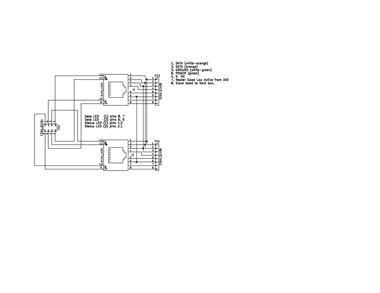
RS-485 Communication is handled by a Module which contains a MAX485ESA. Interconnecting the RS485 multi-drop is accomplished by a pair of RJ45 connectors with status LEDs (they must not have any magnetics). The module just plugs into a pair of 1x4 headers on the baseboard. I am using standard ethernet jumpers 12" long. (this preserves the twist for RS-485 (specified in the spec). The pair of RJ45 jacks are just wired to each other pin to pin (see RS-485 Interconnect Wiring Table).

The Status LED is light from a CPU GPIO after initialization.

The Data Monitor LED is connected to the Arduino's RX1 and TX1. It really doesn't matter as only one will be high at a time.  The Inputs to the RS-485 module are also these ports as well.

There is also a dip-switch (4 poles){only on slaves} that is used on the slaves to identify the slave to the master.

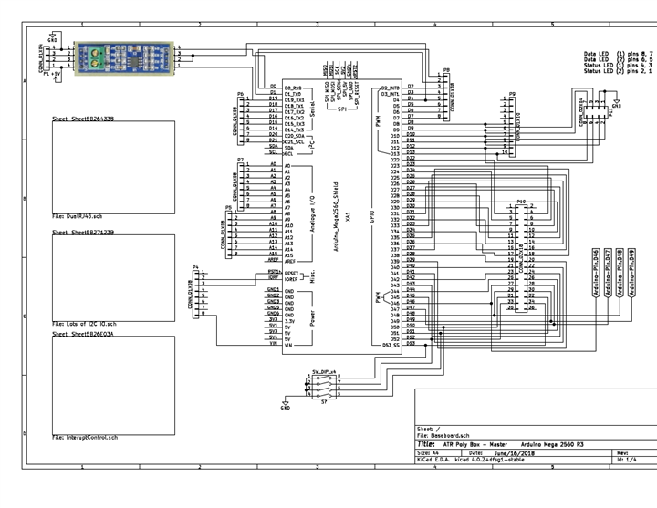
As I got feed up with eagleCAD I am now using KiCAD. KiCAD has an almost Zero learning curve. This is my first drawing with KiCAD, it's hierarchical and I am showing the baseboard itself, and the dual RJ45 Module.


Stay Tuned More to Come

~ Cris H. image


Addendum: Final Thoughts, One quirk that KiCAD has is its export function. It only exports as a PDF life (with a transparent background (you know the black and gray checkerboard) which is in its self a problem well you can see the damn thing. So first I tried image magic, that gets me to a png file but still with the background. So I grabbed my swiss knife gimp and opened it in layers. So now all you do is export it and turn off the background in the dialog. - fins.


Back to the Indeximage

imageimage

  • Sign in to reply

Top Comments

  • DAB
    DAB over 7 years ago +1
    Nice update. Good idea on the KiCad output. I find Gimp very resourceful when dealing with images. I also like the idea of using the ethernet connectors. Readily available and the cable now goes for a…
  • DAB
    DAB over 7 years ago

    Nice update.


    Good idea on the KiCad output.

    I find Gimp very resourceful when dealing with images.


    I also like the idea of using the ethernet connectors. Readily available and the cable now goes for a good price.


    DAB

    • Cancel
    • Vote Up +1 Vote Down
    • Sign in to reply
    • More
    • Cancel
element14 Community

element14 is the first online community specifically for engineers. Connect with your peers and get expert answers to your questions.

  • Members
  • Learn
  • Technologies
  • Challenges & Projects
  • Products
  • Store
  • About Us
  • Feedback & Support
  • FAQs
  • Terms of Use
  • Privacy Policy
  • Legal and Copyright Notices
  • Sitemap
  • Cookies

An Avnet Company © 2025 Premier Farnell Limited. All Rights Reserved.

Premier Farnell Ltd, registered in England and Wales (no 00876412), registered office: Farnell House, Forge Lane, Leeds LS12 2NE.

ICP 备案号 10220084.

Follow element14

  • X
  • Facebook
  • linkedin
  • YouTube