


Well, here I am again so let you all in whats really going on. I need a dual Throttle Quadrant. As I have said before I have 2 of them.
So here is the PLAN:
Now I distrust USB as when it fails you cant trust the configurations anymore. So I will communicate via RS-485 between Arduinos, with the master node,
using NASA's EADIN Lite Protocol.
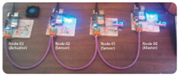
having an Ethernet interface, to talk to the simulator. So far I have 3 nodes:
- Master: runs joystick and talks to the simulator via ethernet and talks RS-485 to the slaves

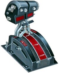
- Slave.1: runs Throttle Quadrant, Gear Lever, and Gear Lights
- Slave.2: runs Rudder and Brakes
- Slave.3: runs Engine Start Panel, Computer Fail-Over Panel
| Connector | Pins | Functions | D/A | Pins |
|---|---|---|---|---|---|
| L | 1 | Left Multi-Function Switch | PA0 | 78 | |
| L | 2 | Trim Wheel (wiper) | ADC8 | 89 | |
| L | 3, 4 | Pinky Switch | PA1 PA2 | 77 76 | |
| L | 6 | 5+ volts | |||
| L | 7 | Ground | |||
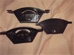
| R | 1, 4 | JoyStick 1 Note should convert to an analog joystick | PB0 PB1 PB2 PB3 | 19 20 21 22 | |
| R | 5, 8 | JoyStick 2 Note should convert to an analog joystick | PB4 PB5 PB6 PB7 | 23 24 25 26 | |
| R | 9, 10 | Mic Switch | PC0 PC1 | 53 54 | |
| R | 11, 12 | Coolie Hat, | PC2 PC3 | 55 56 | |
| R | 13, 14 | Boat Switch | PC4 PC5 | 57 58 | |
| R | 15,16 | Mode Switch | PC6 PC7 | 59 60 | |
| R | 20 | 5+ volts | |||
| R | 25 | Ground | |||
| C | 1 | Right Power Lever | ADC9 | 88 | |
| C | 2 | Left Power Lever | ADC10 | 87 | |
| C | 3 | Right Fuel Switch | PG0 | 51 | |
| C | 4 | Left Fuel Switch | PG1 | 52 | |
| C | 5 | Right AB Switch | PG2 | 70 | |
| C | 6 | Left AB Switch | PL0 | 35 | |
| C | 7 | 5+ volts | |||
| C | 9 | Ground | |||
| G | 1 | Landing Gear Lever | PL1 | 36 | |
| G | 2 | Gear, Nose | PL2 | 37 | |
| G | 3 | Gear, Main, Right | PL3 | 38 | |
| G | 4 | Gear, Main, Left | PL4 | 39 | |
| G | 5 | 5+ volts | |||
| G | 6 | Ground | |||
Series Index: | |||||
 |
Arduino microcontrollers communicating with EADIN Lite protocol for real-time sensing and actuation. |


~ CA Harrison 
PS. More to come!
Top Comments