 Ok, here we go again. This is a fresh (not quite) start Jan 2025 I have lost all of my work on the sim! So here we go one more time. Here is what I am up against.
- There are 4 Alphanumeric 16 digit displays these can be driven by 4 x MCP23S17 and some BJT(s).
- There are 13 Numeric 7 digit displays these can be broken up into 2 sets of 4 plus 1 set of 5. These can be now driven with 3 74247(s) plus BJT(s). These in tern will be driven by 3 half of 74LS244(s) the extra half will drive the other 3. (74143 might eliminate the BJT(s) but I have to double check the ratings of each segment.
- I need a display selector, which are 3 74LS138(s) which are chained together to give me a 24-bit decoder with out external logic.
- ADDENDUM 1/22/25: So now you know there are 17 displays. SIDE NOTE: To make the display NOT TO FLICKER, The whole thing has to run at less than .25 seconds Ouch! wait I said the 4 Alphanumeric displays are driven by 4 x MCP23S17(s) which means that its only 17 displays and they have to be driven less that .25 seconds. MATH: 17 x .25 sec = 4.25 sec so we have to be a lot faster
- 1 need to output 2 BCD thumbwheel switches to a bus.
- 1 need to output my two rotary switch to a bus
- problem 4 & 5 is solved again with my trusty MCP23S17 but the output of the rotary switches need to be handed by 2 priority encoders which give me BCD outputs. (74LS147 or 74LS148)
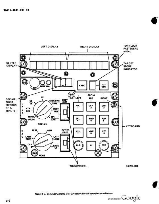
- Then you have a keyboard:( The problem it self is the way it works you see ( first row: A B C) normal stuff but it isn't! you see you need to keep track of the column and the row! Now back in day I wrote in C a state table to handle this, as there are 17 keys and 4 of them are special. From TM11 5841-281-12: "To display a number, press the corresponding key or keys ( 1 through 0). To display a letter, first press the key corresponding to the desired letter; then press a key in the left, mid, or right column corresponding to the position of the letter on the key. Example: To enter an L, first press L, then 3, 6, or 9 in the right column." Now while this nonsense is going on you also have to deal with the fact that the display is really 3 displays! I have included a print of the front panel for your entertainment.
- Of course I would love to use 2 Arduino Mega(s), Now this is going to get busy, the display and the keyboard most likely be handled by one unit. and the other would handle the four switches plus communication to the host most likely this will be Ethernet I don't know If I want to run CAN aerospace on top of it or my own packet, as this is cumming from the simulation model where I need the following: Speed over the ground, Altitude, Heading, Roll and Yaw (aircraft states), plus Heading, (on the ground) and for good measure we can toss in the Accelerations (vectors), and some other stuff. TBD (To Be Determined) .
- One last little thing, we need inter-process communications as well. that is between the two CPU's. And lastly there has to be a CANaerospace Interface on this beast as well. Problem: I have never seen a CAN interface and a Ethernet interface on one Arduino. have you??
- ADDENDUM! this will need a lot of interrupts so I will resort to a very dirty trick multi-layer interrupts! That is to say I have a priority encoder wired to the MCP23S17(s) interrupt lines that 4 so we need four bits 1, 2, 3, 4 this goes through a 4 input exclusive OR whose output can now go to one interrupt.
- EXPLANATION: So we need 8 bits for the port the address. First the Interrupt number 1-4 is written to the port and then the CPU signals to route the data to the same port. So that is 2 reads and 1 bit written after the interrupt pin is pulled down! I am very tired and I'[m going to bed to decubitus (from Latin decumbo 'to lie down') !
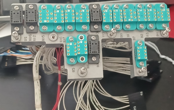
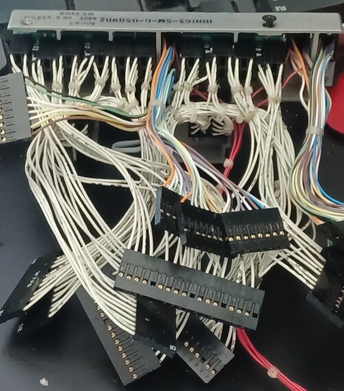
EXTRA, EXTRA!! Pretty Pictures!!!! (TG I have the other half of the harness.. Still a lot of work.