element14 Community
element14 Community
    Register Log In
  • Site
  • Search
  • Log In Register
  • Community Hub
    Community Hub
    • What's New on element14
    • Feedback and Support
    • Benefits of Membership
    • Personal Blogs
    • Members Area
    • Achievement Levels
  • Learn
    Learn
    • Ask an Expert
    • eBooks
    • element14 presents
    • Learning Center
    • Tech Spotlight
    • STEM Academy
    • Webinars, Training and Events
    • Learning Groups
  • Technologies
    Technologies
    • 3D Printing
    • FPGA
    • Industrial Automation
    • Internet of Things
    • Power & Energy
    • Sensors
    • Technology Groups
  • Challenges & Projects
    Challenges & Projects
    • Design Challenges
    • element14 presents Projects
    • Project14
    • Arduino Projects
    • Raspberry Pi Projects
    • Project Groups
  • Products
    Products
    • Arduino
    • Avnet & Tria Boards Community
    • Dev Tools
    • Manufacturers
    • Multicomp Pro
    • Product Groups
    • Raspberry Pi
    • RoadTests & Reviews
  • About Us
  • Store
    Store
    • Visit Your Store
    • Choose another store...
      • Europe
      •  Austria (German)
      •  Belgium (Dutch, French)
      •  Bulgaria (Bulgarian)
      •  Czech Republic (Czech)
      •  Denmark (Danish)
      •  Estonia (Estonian)
      •  Finland (Finnish)
      •  France (French)
      •  Germany (German)
      •  Hungary (Hungarian)
      •  Ireland
      •  Israel
      •  Italy (Italian)
      •  Latvia (Latvian)
      •  
      •  Lithuania (Lithuanian)
      •  Netherlands (Dutch)
      •  Norway (Norwegian)
      •  Poland (Polish)
      •  Portugal (Portuguese)
      •  Romania (Romanian)
      •  Russia (Russian)
      •  Slovakia (Slovak)
      •  Slovenia (Slovenian)
      •  Spain (Spanish)
      •  Sweden (Swedish)
      •  Switzerland(German, French)
      •  Turkey (Turkish)
      •  United Kingdom
      • Asia Pacific
      •  Australia
      •  China
      •  Hong Kong
      •  India
      • Japan
      •  Korea (Korean)
      •  Malaysia
      •  New Zealand
      •  Philippines
      •  Singapore
      •  Taiwan
      •  Thailand (Thai)
      • Vietnam
      • Americas
      •  Brazil (Portuguese)
      •  Canada
      •  Mexico (Spanish)
      •  United States
      Can't find the country/region you're looking for? Visit our export site or find a local distributor.
  • Translate
  • Profile
  • Settings
Personal Blogs
  • Community Hub
  • More
Personal Blogs
NexGen Flight Simuator Soldering School - part 3: The Cable Multi-Purpose Color Display (F/A-18C/D MPCD)
  • Blog
  • Documents
  • Mentions
  • Sub-Groups
  • Tags
  • More
  • Cancel
  • New
  • Share
  • More
  • Cancel
Group Actions
  • Group RSS
  • More
  • Cancel
Engagement
  • Author Author: phoenixcomm
  • Date Created: 24 Sep 2014 3:43 AM Date Created
  • Views 524 views
  • Likes 3 likes
  • Comments 3 comments
  • hardware
  • repair
  • nexgen_flight_simulator
  • nasa-std-8739.3
  • soldering
  • nasa-std-8739.4
  • cabling
  • diy_cockpit
  • feature_tutorial
Related
Recommended

Soldering School - part 3: The Cable Multi-Purpose Color Display (F/A-18C/D MPCD)

phoenixcomm
phoenixcomm
24 Sep 2014

Well here we are again, I know your going to ask me why am I making a post just for this dam cable???image

image
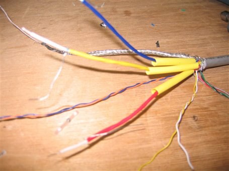
The cable that had a short in it.
Figure 1

THE ANALYSIS: As you may know back in February I said "It looks like there was a whisker shorting out the Blue.. GROAN: Ok the fix is painful. I have to cut down the shrink wrap and then the electrical tape and two layers of shrink wrap over the Blue itself." So being lazy I did repair the cable by opening the green layer and then re-soldered the blue but I "rigged it" LOL. At the end of August, I went to Cockpit Fest with the Cable as you guessed I never fixed the *** Cable, so its time to do something about it..  I really want this to be a pro. so I just cut the cable in half time to start over and just do it right.

THE PLAN:

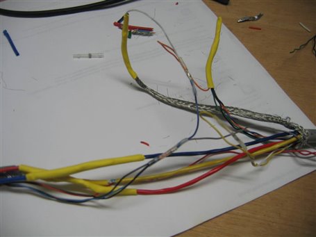
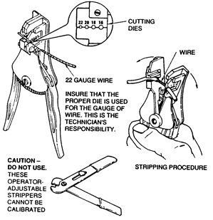
  1. Cut the cable in twain and re-strip the wires. Please see Figure 3 for the proper tools.
  2. Obtain the proper solder splice (see Figure 2).  They can be found on eBay with the search term "solder sleeve".  You will notice that it is a heat shrink tube with solder in it. Here is a nice little video that demonstrates the proper technique for applying the but splice. (Video below). Please see NASA-STD-8739.4 March 2011 page 83 #19.8
  3. First, we have to slide a new piece of shrink wrap on the cable.  This will be used as the outer sheath.
  4. We will also side a piece of shrink wrap on each one of the Red, Green, and Blue.
    1. Now use the solder sleeves to solder the three (3) drive wires  (coax centers).
    2. Now solder the three (3) shields (don't need but splices).
    3. Now install the  yellow  shrink tubing  over the shields
  5. Now use the solder sleeves to solder the two (2) sync lines together.
  6. Also, solder any other remaining wires as per Table 1.
  7. shrink any tubing over the other connections.'
  8. Pull into place the outer shrink tube and shrink it.
image
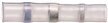
Solder Sleeve
Figure 2


Keep Tuned in.. More To Come!

image  Cris


Signals PS3 Cable VGA Cable
RED RED RED
GREEN GREEN YELLOW
BLUE BLUE BLUE
SYNC blue Tan
SYNC red red


Yellow
white


Black

Black

Green
Blue
Black

Orange


Soldering Guide
Table 1

You don't have permission to edit metadata of this video.
Edit media
x
image
Upload Preview
image


Mechanical Stripper Thermal Strippers
image image
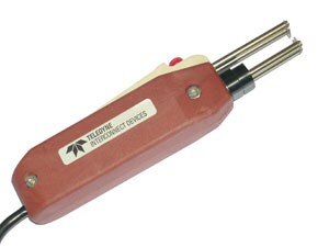
Wire Strippers
Figure 3

References:

  • NASA-STD-8739.3  Feb 1998  Soldered Electrical Connections
  • NASA-STD-8739.4  Feb 1998  Crimping, Interconnecting Cables, Harnesses, and Wiring.
  • NASA-STD-8739.4  Mar 2011  Crimping, Interconnecting Cables, Harnesses, and Wiring
  • NASA Training Program          Student Workbook for Hand Soldering


I will be posting pics of the steps here...
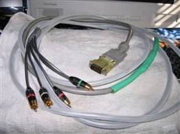


The Cable

Photos


PS3 cableimage

(1-3)


VGA cableimage

(3-4)


Cable trim is too shortimage

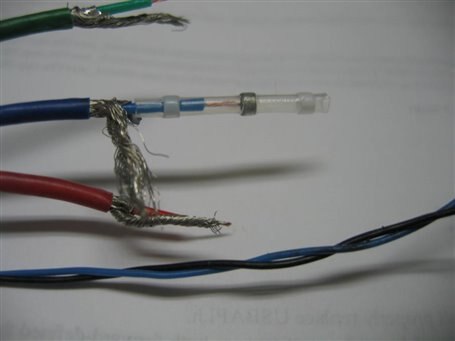
Proper installation of solder sleeve

(4.1, 4.2)

image

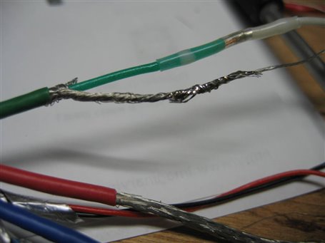
Shrink tube over the solder sleeve and shield

(4.3)
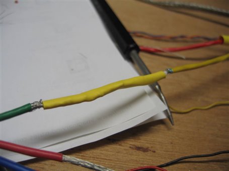
image

Groundsimage

(8,9)

Pulling the outer sleeve over the wire splices

(sorry for the blurry pic)

(10)
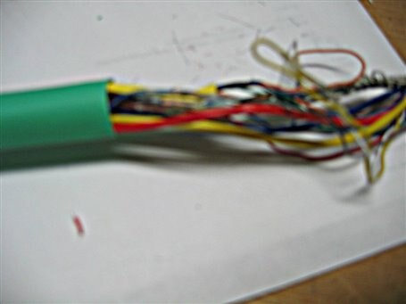
image
  • Sign in to reply
  • phoenixcomm
    phoenixcomm over 11 years ago in reply to shabaz

    thanks, look at the student guide for more of the how to guide... The STDs are the Bible

    • Cancel
    • Vote Up 0 Vote Down
    • Sign in to reply
    • More
    • Cancel
  • shabaz
    shabaz over 11 years ago

    Hi Cris,

    Thanks to the link to the document, this looks great - looking forward to going through it. There is clearly decades of experience in there, so well worth studying.

    • Cancel
    • Vote Up 0 Vote Down
    • Sign in to reply
    • More
    • Cancel
  • DAB
    DAB over 11 years ago

    Hi Chris,


    Good post.

    I would add here that 50% of avionics failures are due to cable issues.

    Between a bad wire in a cable, the wrong cable connected to the wrong box, and just loose cable connections, well you get the picture.

    The best device in the world cannot work if its not plugged in properly.


    So I am glad that you emphasized the cable issue.  It bites nearly every project at one point or another.


    DAB

    • Cancel
    • Vote Up 0 Vote Down
    • Sign in to reply
    • More
    • Cancel
element14 Community

element14 is the first online community specifically for engineers. Connect with your peers and get expert answers to your questions.

  • Members
  • Learn
  • Technologies
  • Challenges & Projects
  • Products
  • Store
  • About Us
  • Feedback & Support
  • FAQs
  • Terms of Use
  • Privacy Policy
  • Legal and Copyright Notices
  • Sitemap
  • Cookies

An Avnet Company © 2026 Premier Farnell Limited. All Rights Reserved.

Premier Farnell Ltd, registered in England and Wales (no 00876412), registered office: Farnell House, Forge Lane, Leeds LS12 2NE.

ICP 备案号 10220084.

Follow element14

  • X
  • Facebook
  • linkedin
  • YouTube