element14 Community
element14 Community
    Register Log In
  • Site
  • Search
  • Log In Register
  • About Us
  • Community Hub
    Community Hub
    • What's New on element14
    • Feedback and Support
    • Benefits of Membership
    • Personal Blogs
    • Members Area
    • Achievement Levels
  • Learn
    Learn
    • Ask an Expert
    • eBooks
    • element14 presents
    • Learning Center
    • Tech Spotlight
    • STEM Academy
    • Webinars, Training and Events
    • Learning Groups
  • Technologies
    Technologies
    • 3D Printing
    • FPGA
    • Industrial Automation
    • Internet of Things
    • Power & Energy
    • Sensors
    • Technology Groups
  • Challenges & Projects
    Challenges & Projects
    • Design Challenges
    • element14 presents Projects
    • Project14
    • Arduino Projects
    • Raspberry Pi Projects
    • Project Groups
  • Products
    Products
    • Arduino
    • Avnet Boards Community
    • Dev Tools
    • Manufacturers
    • Multicomp Pro
    • Product Groups
    • Raspberry Pi
    • RoadTests & Reviews
  • Store
    Store
    • Visit Your Store
    • Choose another store...
      • Europe
      •  Austria (German)
      •  Belgium (Dutch, French)
      •  Bulgaria (Bulgarian)
      •  Czech Republic (Czech)
      •  Denmark (Danish)
      •  Estonia (Estonian)
      •  Finland (Finnish)
      •  France (French)
      •  Germany (German)
      •  Hungary (Hungarian)
      •  Ireland
      •  Israel
      •  Italy (Italian)
      •  Latvia (Latvian)
      •  
      •  Lithuania (Lithuanian)
      •  Netherlands (Dutch)
      •  Norway (Norwegian)
      •  Poland (Polish)
      •  Portugal (Portuguese)
      •  Romania (Romanian)
      •  Russia (Russian)
      •  Slovakia (Slovak)
      •  Slovenia (Slovenian)
      •  Spain (Spanish)
      •  Sweden (Swedish)
      •  Switzerland(German, French)
      •  Turkey (Turkish)
      •  United Kingdom
      • Asia Pacific
      •  Australia
      •  China
      •  Hong Kong
      •  India
      •  Korea (Korean)
      •  Malaysia
      •  New Zealand
      •  Philippines
      •  Singapore
      •  Taiwan
      •  Thailand (Thai)
      • Americas
      •  Brazil (Portuguese)
      •  Canada
      •  Mexico (Spanish)
      •  United States
      Can't find the country/region you're looking for? Visit our export site or find a local distributor.
  • Translate
  • Profile
  • Settings
Personal Blogs
  • Community Hub
  • More
Personal Blogs
Nico teWinkel's Blog Soldering a tiny LED using a Digital Microscope
  • Blog
  • Documents
  • Mentions
  • Sub-Groups
  • Tags
  • More
  • Cancel
  • New
  • Share
  • More
  • Cancel
Group Actions
  • Group RSS
  • More
  • Cancel
Engagement
  • Author Author: ntewinkel
  • Date Created: 24 May 2021 9:54 PM Date Created
  • Views 2362 views
  • Likes 10 likes
  • Comments 10 comments
  • koolertron
  • smd
  • led
  • microscope
  • soldering
  • digital microscope
Related
Recommended

Soldering a tiny LED using a Digital Microscope

ntewinkel
ntewinkel
24 May 2021

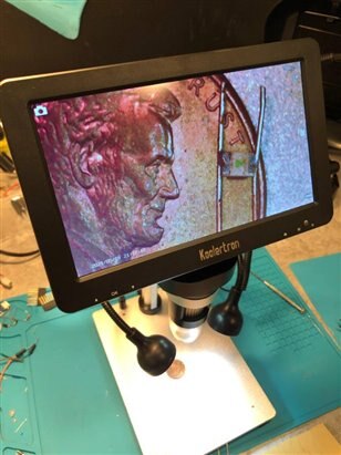
In an earlier blog post, I mentioned my new tech toy: a relatively affordable little 7" digital microscope I bought on Amazon.


A few people were curious as to how effective my new little digital "Koolertron" microscope would be for soldering.

As some people in the past have mentioned, digital microscopes can have a bit of lag which can make doing anything like soldering impossible or at least terribly annoying.

I've actually found it to be quite nice to use. Now, I'm no expert, so others with quicker reflexes might feel lag that I don't notice image


So I took some video of my very shaky attempt at soldering a tiny smd. I think it's 0402 ? it's smaller than the 0603 ones that were marked. In any case, at one point I obviously thought it was a good idea to buy some impossibly tiny smd LEDs for some future impossibly tiny projects. Life lessons abound.


Here are a few more learning opportunities that I will share right now, as I made several mistakes in this soldering project that made things very difficult:

1. solder flux. sigh. don't forget the flux, even on those little parts. especially on those little parts

2. find a way to secure the little parts, or else they will just stick to the solder on the iron.


That explains the burnt look on the finished LED image


In any case, I eventually saw the folly of my ways and life got easier. I'll spare you the very frustrating parts, and just share a few short videos so you can kind of see it in action.


The result worked out well enough, though it wasn't pretty image

image


I use magnet wire with smd LEDs for use in art type projects, as the wire is much thinner than regular type wire, and the lacquer coating keeps it from shorting out.

I find it easiest to just burn off some of the lacquer at the spots you need to solder or connect to battery.


Bit of an intro/overview first:

You don't have permission to edit metadata of this video.
Edit media
x
image
Upload Preview
image


Here is my messy attempt. it's cool to see how much messier things are when they are enlarged with the microscope image

I think this might have been try number 5 or so, after the forgotten flux and the silly attempt at loose soldering.

You don't have permission to edit metadata of this video.
Edit media
x
image
Upload Preview
image


And finally, showing the LED actually working - success!!

You don't have permission to edit metadata of this video.
Edit media
x
image
Upload Preview
image


Cheers,

-Nico

  • Sign in to reply

Top Comments

  • colporteur
    colporteur over 4 years ago in reply to shabaz +5
    I had an orthodontists modify a pair of dental tweezers from his toolbox, to make these flat tip babies. The tip is normally closed, pinch to open. They are super thin and have a smooth surface. They actually…
  • neilk
    neilk over 4 years ago +3
    Hi Nico, Great! That video was very tense - you were whispering and I was holding my breath in case I blew the LED away!! Thanks for sharing the enormous difference that the microscope made. Neil
  • geralds
    geralds over 4 years ago +3
    Hi Nico, fine job. One idea: fix one tinned copper wire on the board-desk then lay the pin of the LED on this wire and melt them by heating the wire. The LED will sinking into the tin. Then do the same…
  • dubbie
    dubbie over 4 years ago

    Nico,


    Thanks for this, these were very helpful videos. It is good to see how clear the video seems to be while actually trying to solder. I still think your soldering is pretty good - compared to mine on some pin through hole components. I'm not too bad with 60:40 solder but I do find anything else just doesn't seem to work as well. Not sure why.  I have some 63:37 solder and it just seems so much more difficult to use. Maybe the internal flux is different, or something.


    However, the idea of using a magnifying camera system does seem to be something I will have to look into for soldering and maybe other things as well. The magnification and clarity seem just great.


    Dubbie

    • Cancel
    • Vote Up +2 Vote Down
    • Sign in to reply
    • More
    • Cancel
  • colporteur
    colporteur over 4 years ago in reply to shabaz

    I had an orthodontists modify a pair of dental tweezers from his toolbox, to make these flat tip babies. The tip is normally closed, pinch to open. They are super thin and have a smooth surface. They actually close to hold one side of the 402 LED to enable soldering the other side.


    I appreciate your commentary on misplacing your tweezers. These were at one site and I was at another. I carried the material to the other side to use the tweezers:)

    image

    • Cancel
    • Vote Up +5 Vote Down
    • Sign in to reply
    • More
    • Cancel
  • shabaz
    shabaz over 4 years ago in reply to ntewinkel

    Hi Nico,


    The tweezer style below seems reliable to me, although some might prefer angled ones, etc.

    I don't think I have any 0402 LEDs, but I had 0603 and 0402 capacitors, as shown in the photo below, the 0603 is gripped with it.


    It is >10 years old, I don't think these particular ones (VOMM brand) are made any more, but are labelled "PSF SA" which might be (not 100% sure) a general tweezer size/shape code that other manufacturers make too.

    image

    They have a squared-off flat end that is about 0.8mm wide measured with calipers. Each time I misplace them, I feel totally lost trying to do surface-mount, so from my perspective they made a big difference to me.

    image

    • Cancel
    • Vote Up +2 Vote Down
    • Sign in to reply
    • More
    • Cancel
  • ntewinkel
    ntewinkel over 4 years ago in reply to colporteur

    colporteur  wrote:


    Great update. I have soldered the 402 LED freehand. I watched a few Youtube videos to get an idea. Yes, securing the LED is import and your realization of the need for flux.


    I use the 402 LED often in HQ scale model railroad. Car lights or vehicle obstruction lights are typical. Using the lacquered winding wire. 0.1mm is what has proven best for me. 


    I tip my hat to you for your mad soldering skillz! image


    Those tiny LEDs open up a world of hobbyist/artist options don't they?


    How do you remove the lacquer from the wire for soldering? I tried fine sandpaper, nail polish remover, paint thinner, but ultimately the big hammer approach of fire seems to work most reliably, even if it's not very accurate, followed up with sandpaper to remove any soot.

    It could also be that I'm reusing wire from old transistors... that might be harder to work with.


    Best,

    -Nico

    • Cancel
    • Vote Up +1 Vote Down
    • Sign in to reply
    • More
    • Cancel
  • ntewinkel
    ntewinkel over 4 years ago in reply to geralds

    geralds  wrote:


    One idea: fix one tinned copper wire on the board-desk then lay the pin of the LED on this wire and melt them by heating the wire. The LED will sinking into the tin.


    Oh that's a good idea.. you mean like add a bit extra solder tinning to the wire, and then heating the wire further up with the iron will re-melt the solder that's on the wire onto the LED?


    >If you use a tin wire (<=1mm_dia) with rosin, you do not need extra rosin, because this "explode" and the parts will jumping away.

    I never thought of that effect. I think I do have some thinner solder wire I can try too.


    I also bought some smd solder paste a while ago... I wonder if that might work well too.


    Thanks for the tips!

    -Nico

    • Cancel
    • Vote Up +1 Vote Down
    • Sign in to reply
    • More
    • Cancel
>
element14 Community

element14 is the first online community specifically for engineers. Connect with your peers and get expert answers to your questions.

  • Members
  • Learn
  • Technologies
  • Challenges & Projects
  • Products
  • Store
  • About Us
  • Feedback & Support
  • FAQs
  • Terms of Use
  • Privacy Policy
  • Legal and Copyright Notices
  • Sitemap
  • Cookies

An Avnet Company © 2025 Premier Farnell Limited. All Rights Reserved.

Premier Farnell Ltd, registered in England and Wales (no 00876412), registered office: Farnell House, Forge Lane, Leeds LS12 2NE.

ICP 备案号 10220084.

Follow element14

  • X
  • Facebook
  • linkedin
  • YouTube