element14 Community
element14 Community
    Register Log In
  • Site
  • Search
  • Log In Register
  • About Us
  • Community Hub
    Community Hub
    • What's New on element14
    • Feedback and Support
    • Benefits of Membership
    • Personal Blogs
    • Members Area
    • Achievement Levels
  • Learn
    Learn
    • Ask an Expert
    • eBooks
    • element14 presents
    • Learning Center
    • Tech Spotlight
    • STEM Academy
    • Webinars, Training and Events
    • Learning Groups
  • Technologies
    Technologies
    • 3D Printing
    • FPGA
    • Industrial Automation
    • Internet of Things
    • Power & Energy
    • Sensors
    • Technology Groups
  • Challenges & Projects
    Challenges & Projects
    • Design Challenges
    • element14 presents Projects
    • Project14
    • Arduino Projects
    • Raspberry Pi Projects
    • Project Groups
  • Products
    Products
    • Arduino
    • Avnet Boards Community
    • Dev Tools
    • Manufacturers
    • Multicomp Pro
    • Product Groups
    • Raspberry Pi
    • RoadTests & Reviews
  • Store
    Store
    • Visit Your Store
    • Choose another store...
      • Europe
      •  Austria (German)
      •  Belgium (Dutch, French)
      •  Bulgaria (Bulgarian)
      •  Czech Republic (Czech)
      •  Denmark (Danish)
      •  Estonia (Estonian)
      •  Finland (Finnish)
      •  France (French)
      •  Germany (German)
      •  Hungary (Hungarian)
      •  Ireland
      •  Israel
      •  Italy (Italian)
      •  Latvia (Latvian)
      •  
      •  Lithuania (Lithuanian)
      •  Netherlands (Dutch)
      •  Norway (Norwegian)
      •  Poland (Polish)
      •  Portugal (Portuguese)
      •  Romania (Romanian)
      •  Russia (Russian)
      •  Slovakia (Slovak)
      •  Slovenia (Slovenian)
      •  Spain (Spanish)
      •  Sweden (Swedish)
      •  Switzerland(German, French)
      •  Turkey (Turkish)
      •  United Kingdom
      • Asia Pacific
      •  Australia
      •  China
      •  Hong Kong
      •  India
      •  Korea (Korean)
      •  Malaysia
      •  New Zealand
      •  Philippines
      •  Singapore
      •  Taiwan
      •  Thailand (Thai)
      • Americas
      •  Brazil (Portuguese)
      •  Canada
      •  Mexico (Spanish)
      •  United States
      Can't find the country/region you're looking for? Visit our export site or find a local distributor.
  • Translate
  • Profile
  • Settings
Personal Blogs
  • Community Hub
  • More
Personal Blogs
Rachael's Blog Lab Experiments - The Mystery of the Magic Smoke from the LM2596 DC-DC Converter Board Solved
  • Blog
  • Documents
  • Mentions
  • Sub-Groups
  • Tags
  • More
  • Cancel
  • New
  • Share
  • More
  • Cancel
Group Actions
  • Group RSS
  • More
  • Cancel
Engagement
  • Author Author: rachaelp
  • Date Created: 8 Feb 2017 2:00 PM Date Created
  • Views 2096 views
  • Likes 4 likes
  • Comments 6 comments
Related
Recommended

Lab Experiments - The Mystery of the Magic Smoke from the LM2596 DC-DC Converter Board Solved

rachaelp
rachaelp
8 Feb 2017

Overview


For those of you that saw my blog yesterday on my experiments with a cheap LM2596S based DC-DC converter board you are no doubt aware that under one of the test conditions my first test board emitted the magic smoke. If you haven't seen that already I suggest you go and take a look there first:


Lab Experiments - Performance Evaluation and Testing of LM2596 DC-DC Converter Board


I was setting up my second board today so I could continue where I left off and get that blog finished off when I discovered something in my test setup which explains a lot.


Test Setup


I described the test setup yesterday but for completeness I will cover the important sections here again.


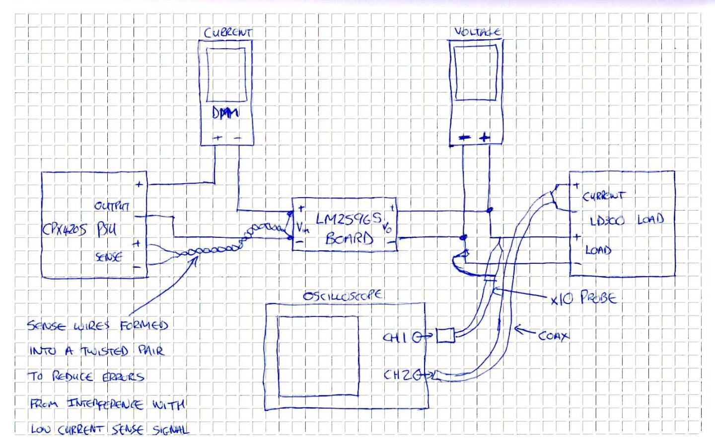
The input of the LM2596S board will be from the TTi  CPX400SCPX400S Power Supply The KeySight https://www.element14.com/community/view-product.jspa?fsku=1848657&nsku=NULL&COM=noscriptU1272A will be wired in series with the positive input voltage to measure the input current. The remote sense will connect directly at the input of the board such that it will compensate for any losses in the cable and also the burden voltage of the ammeter As stated previously with this compensated supply voltage the input voltage will be read directly from the set voltage on the power supply


The test setup is shown below:


image


The Problem


There are two important things to note from the setup above:


  1. The remote sense is being used to compensate for voltage drops in cables and the burden voltage of the multimeter to maintain the voltage accurately at the input to the board.
  2. The Keysight  U1272AU1272A multimeter is in series with the power supply to accurately measure the current flowing into the input


Now, something which is slightly annoying about the Keysight is that it times out and goes to sleep quite quickly, too quickly IMHO. When it switches itself off you have to turn the dial all the way round to the OFF position and then back to where you want it to be.


During testing yesterday I found that if I left the connections as per the above when I was trying to wake it up it would sometimes lock up and then to recover I would have to switch it off and leave it for a few minutes. The first time that happened I did panic a little as I thought I had killed my DMM!


I thought I would solve this by just disconnecting the supply into the meter (pulling it out so to stop it complaining when going through the other switch points) as I was bringing it back to life. This was working fine for most of the testing. Then  as I set up for 40V input (the max operating voltage of the LM2596S) and prepared to rerun the measurements the meter timed out again and I performed the above. Upon resuming testing I discovered the magic smoke was rising up from my bench.


So... back to my first points about the important things to note. Firstly I am using the remote sense so if the voltage at the board is too low the output of the supply will ramp up to compensate. Secondly the multimeter is in series with the power supply so when I pull the lead to reset my meter the voltage at the board drops to 0V.


Do you see where I am going with this?


Theory Number 1:


Sigh.... yes you guessed it, when I pulled the cable to reset the meter the power supply ramped up its output. Upon plugging the cable back in this raised supply voltage was applied to the board and as we were already at the 40V max input the extra voltage killed it.


Theory Number 2:


Naughty Power Supply! Something I noted when connecting the board up to the setup is that connecting the remote sense without having the actual power supply output connected leaves the LM2596S board in a cycle of switching on enough to power it's LED for a second and then going off. I thought this was odd behaviour and was going to come back to investigate at a later date but I just blew board number 2 trying to find out what voltage the power supply reached in the scenario above.... The failure mode of this board is different, this board gives almost no output but consumes 2A and the LM2596S get exceedingly hot.


Conclusion


Now that I have understood the two scenarios which lead to excess input voltage (well above the Abs Max of 45V for the LM2596S) being applied to the board it's probably a little unfair to say that the board doesn't work at the specified 40V input until I have done some further testing on it. I suspect it will work at this input but it remains to be seen whether it is stable and what efficiencies can be achieved. What can be said is that there is no protection on the board to prevent the IC getting damaged by surges over and above the maximum normal working voltage and for a more robust design there perhaps should be. I'll cover this in more depth in a future blog.


I've also learned to remember to remove the 16V rated 470uF electrolytic capacitor from the terminal posts of my power supply before I ramp the supply up to 40V (with a 5A current limit) and turn the output on.... Welcome to magic smoke emissions number two....

  • Sign in to reply

Top Comments

  • mcb1
    mcb1 over 8 years ago in reply to dougw +2
    I knew there was a reason for manuals. I've stuck that back in the 'must remember this' area of the brain and will no doubt forget about it later. Mark
  • rachaelp
    rachaelp over 8 years ago in reply to mcb1 +2
    mcb1 wrote: I knew there was a reason for manuals. Yes, as my Mum used to say "If all else fails, read the instructions".... She's right of course, I should have read the manual.... Anyway, I now have…
  • DAB
    DAB over 8 years ago +1
    Great post. Yes, you have to make a little check list when doing testing. Trust but verify power supplies, input voltages and wire connections. Sometimes the magic smoke is the last thing that escapes…
Parents
  • DAB
    DAB over 8 years ago

    Great post.


    Yes, you have to make a little check list when doing testing.


    Trust but verify power supplies, input voltages and wire connections.


    Sometimes the magic smoke is the last thing that escapes and the damage has already been done.


    Rule of thumb, always adjust the voltage from zero to operating level.


    Never assume that it is at the correct level until you measure that it is there.


    DAB

    • Cancel
    • Vote Up +1 Vote Down
    • Sign in to reply
    • More
    • Cancel
Comment
  • DAB
    DAB over 8 years ago

    Great post.


    Yes, you have to make a little check list when doing testing.


    Trust but verify power supplies, input voltages and wire connections.


    Sometimes the magic smoke is the last thing that escapes and the damage has already been done.


    Rule of thumb, always adjust the voltage from zero to operating level.


    Never assume that it is at the correct level until you measure that it is there.


    DAB

    • Cancel
    • Vote Up +1 Vote Down
    • Sign in to reply
    • More
    • Cancel
Children
  • rachaelp
    rachaelp over 8 years ago in reply to DAB

    DAB wrote:


    Yes, you have to make a little check list when doing testing.


    Trust but verify power supplies, input voltages and wire connections.

    Yes that's good advice. I normally have a test procedure that I follow but I was pressed for time and made a quick variation to get around the annoying multimeter timeout.


    DAB wrote:


    Sometimes the magic smoke is the last thing that escapes and the damage has already been done.


    Rule of thumb, always adjust the voltage from zero to operating level.


    Never assume that it is at the correct level until you measure that it is there.

    Agreed, the problem yesterday was an unforeseen spike in the input voltage due to my last minute procedural variation. I should have thought that one through more as with hindsight it was inevitable!


    The first of today's problems was caused by my power supply remote sense "input" apparently being able to output a voltage back to the DUT when the real output is disconnected. I believe (but didn't verify) that this also happened with the real output turned off.


    Both of these problems were caused because I was using the remote sense function of the CPX400S power supply. The sense wires were soldered to the DUT one end and the remote sense input has really fiddly connectors so I didn't want to have to keep disconnecting and reconnecting them all the time. In future I will try to ensure they are also disconnected when the main output is disconnected. The issue with the voltage being sourced from the remote sense input though is very strange and will probably require some further investigation at some point to see what is going on.


    My second issue today was simply I completely forgot the additional capacitor I had added to the power supply output as it was hidden behind the cables and tucked right up at the output terminal posts and then started adjusting the voltage. I set it to where I wanted with the output disconnected from the DUT then switched it on to check the voltage, it was at this point that the DUT was damaged from voltage being sourced from the remote sense input as well as the unfortunate capacitor expiring in a puff of smoke....

    • Cancel
    • Vote Up 0 Vote Down
    • Sign in to reply
    • More
    • Cancel
element14 Community

element14 is the first online community specifically for engineers. Connect with your peers and get expert answers to your questions.

  • Members
  • Learn
  • Technologies
  • Challenges & Projects
  • Products
  • Store
  • About Us
  • Feedback & Support
  • FAQs
  • Terms of Use
  • Privacy Policy
  • Legal and Copyright Notices
  • Sitemap
  • Cookies

An Avnet Company © 2025 Premier Farnell Limited. All Rights Reserved.

Premier Farnell Ltd, registered in England and Wales (no 00876412), registered office: Farnell House, Forge Lane, Leeds LS12 2NE.

ICP 备案号 10220084.

Follow element14

  • X
  • Facebook
  • linkedin
  • YouTube