This falls in the category of buying and trying something just to see it work.
I first got interested in microcontroller generated video displays back in the late 70s when I had a KIM-1 "single-board computer" which used a 6502 microprocessor (like the Apple 2) and only had a numeric keypad for input and 6 seven segment LEDs for display. Don Lancaster had developed a TV Typewriter project that allowed outputting characters to a video monitor using processor code and some external circuitry (10 ICs).
Here's an image of a Byte ad from Wikipedia:

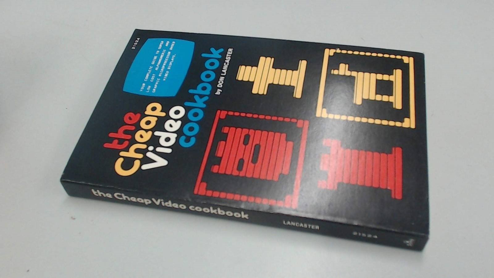
He followed that up with a book in 1978, "The Cheap Video Cookbook" which I discovered is offered as a collectors item on Amazon https://www.amazon.com/Cheap-Video-Cookbook-Donald-Lancaster/dp/0672215241 . Guess I'll have to take good care of my copy  .
.
I saw that Luke Wren had done a project to "bitbang" a DVI interface using the GPIO on the RP2040 https://github.com/Wren6991/PicoDVI .
He even created a PCB to implement it. All the design files are available in the github repo.

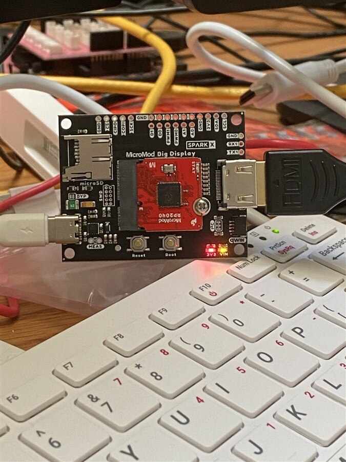
This gave me a feeling of technology enhanced deja vu . I was looking at the Sparkfun RP2040 MicroMod and saw that they had created a MicroMod carrier board that incorporated Luke's design. The MicroMod Big Display Carrier Board https://www.sparkfun.com/products/17718 . The board adds some other features like an SD card socket and a QWIIC interface. On a whim, I decided to buy one and try it out.
I just got an RPi400 and I've set that up to do the code compiling and debug for the RP2040 (initially the Pi Pico and now the MicroMod). For the RPi4 or 400, there is a setup script, pico_setup.sh, that makes the installation of the Pico development environment almost painless. Of course, nothing is without some pain.... The RPi400 came with the OS installed on a 16GB SD card. I had about 6GB free and the Pico environment requires about 2.5GB, so I decided it was probably time to swap to a larger 32GB SD card. This used to be easy - just copy the SD card image using Win32DiskImager, rewrite the image to a larger card, boot the RPi and expand the file system using Raspiconfig. Haven't done this for a while - now there isn't an option to expand the file system... Plan B is to use fdisk and resize2fs to expand the partition, except it doesn't work - finds and fixes orphan inodes, but can't resize the partition. Finally, I gave up and wrote a totally new image to the 32GB card and went through the whole OS setup again. After that everything went smoothly except for taking a bunch of time to do all the downloads.
Got my new boards yesterday.
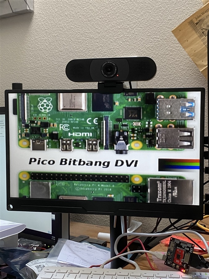
Got ready for some instant gratification as there were a couple of example UF2 files provided. Put the RP2040 MicroMod in mass storage device mode and dragged and dropped the first UF2 file - nothing displayed. Tried the second UF2 file, again nothing. Realizing that this interface is a hack, I try to do diligence - try another cable, try another monitor, try using the DVI interface on the monitor - nothing. I download the PicoDVI repo and compile all the examples. Start trying all the UF2 files - nothing. Somewhat frustrated, I post on the Sparkfun forum - no response. I post an issue on Luke Wren's PicoDVI github repo and he responds within an hour. He even provides me with a UF2 file that he just built and tested. Try his file - and success - shown below.
And a short video of the display:
Of course, nothing is that easy. I had missed an adding a definition to the CMakeLists.txt file -> add_definitions(-DDEFAULT_DVI_SERIAL_CONFIG=micromod_cfg). So, added that and recompiled the PicoDVI repo. Go to try the different examples - nothing. Go back to the good UF2 file - nothing. Now, I'm perplexed. Then I remembered that to test the "good" UF2 file, I had used the monitor that was on the RPi400. I had unplugged the RPi400 HDMI cable and plugged in the carrier board HDMI cable. It turns out that I had swapped the sources quickly enough that the monitor did not attempt to re-validate the HDMI input. Apparently, capacitively coupling the HDMI signals causes the monitor to not recognize the interface and it will shut off. I went back and tried that same experiment with the "good" and "bad" UF2 files and they all worked.
Luke had iterated his design to replace the coupling capacitors with backmatch resistors and he was better able to match the CML logic levels. Unfortunately, the Sparkfun board is based on his first design. I wonder if I'm man enough to swap those little SMD components. I'll have to order some resistors....
In the meantime, here's a few other sample images:
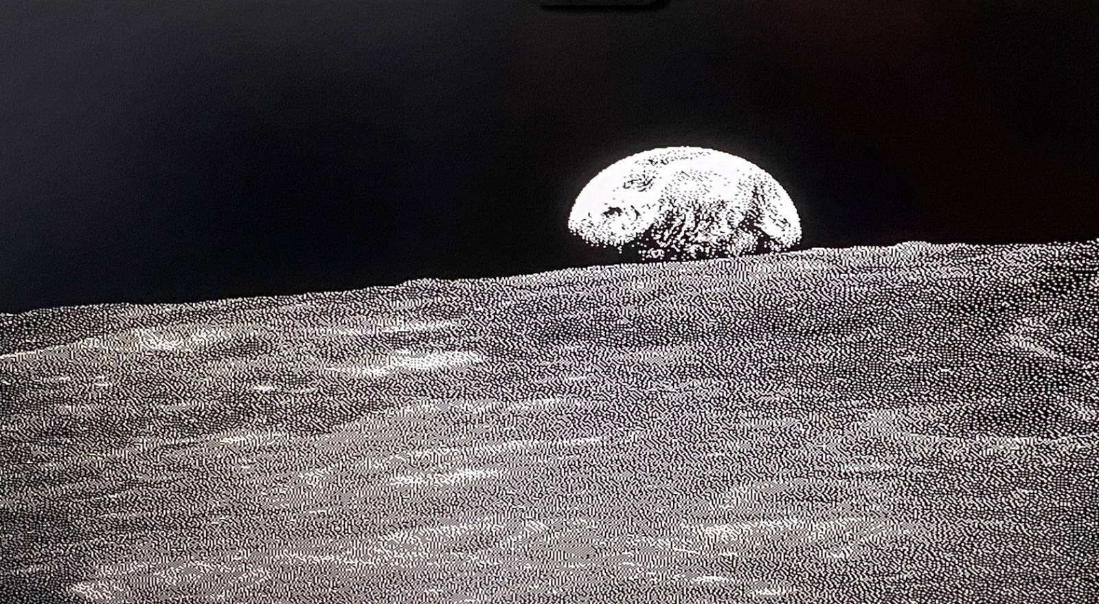
The moon:
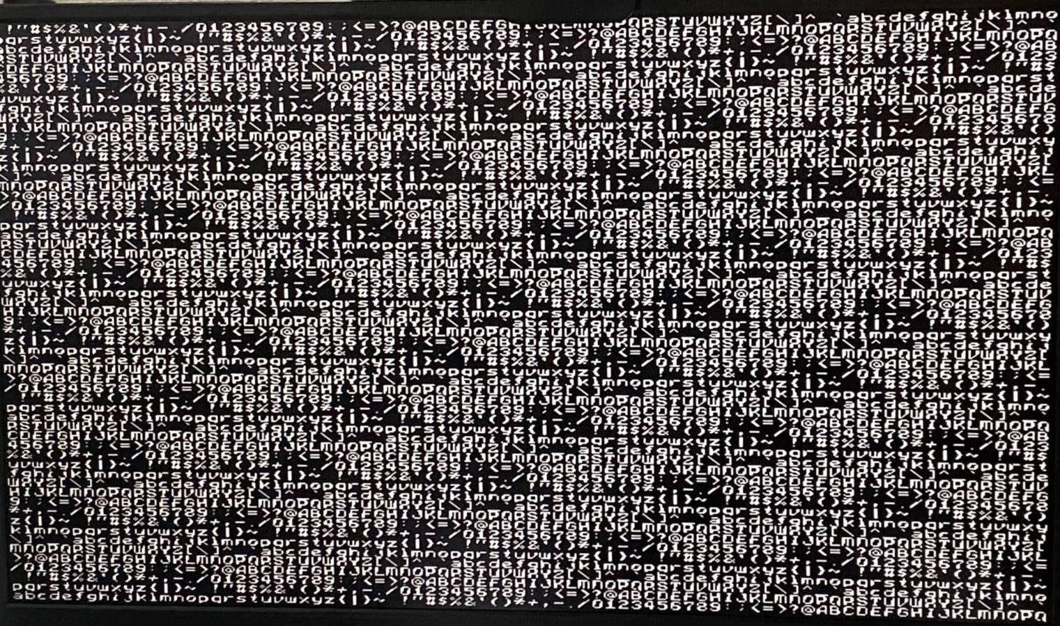
Terminal text:
And a video of Eben's bouncing head:
I ran into some configuration issues, but Luke quickly pointed them out to me. Kudos to Luke for a great project and timely assistance!
So, a bit of nostalgia. I'm sure to have some fun with this.
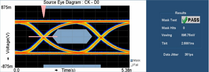
Luke had a nice eye diagram at 372 Mbps (720p30) in his repo. I'm going to have a look at the signals with my scope, but don't the ability to get nice diagrams like this.