Since this power supply has been around since 2015, there is a lot of information about it on the Internet. I thought some on the info that I've come across on the internals of the power supply might be of interest to others. I don't think this info is appropriate for a road test so I'm posting it on my personal blog not the road test blog.
A couple of caveats about this info:
- I would not suggest that anyone open or modify their power supply as that will definitely invalidate the warranty and could create safety issues
- Since I am not opening my unit, I cannot guarantee that all the info is 100% accurate (the PCB pictures are from 2016, the Power switch mod from 2017)
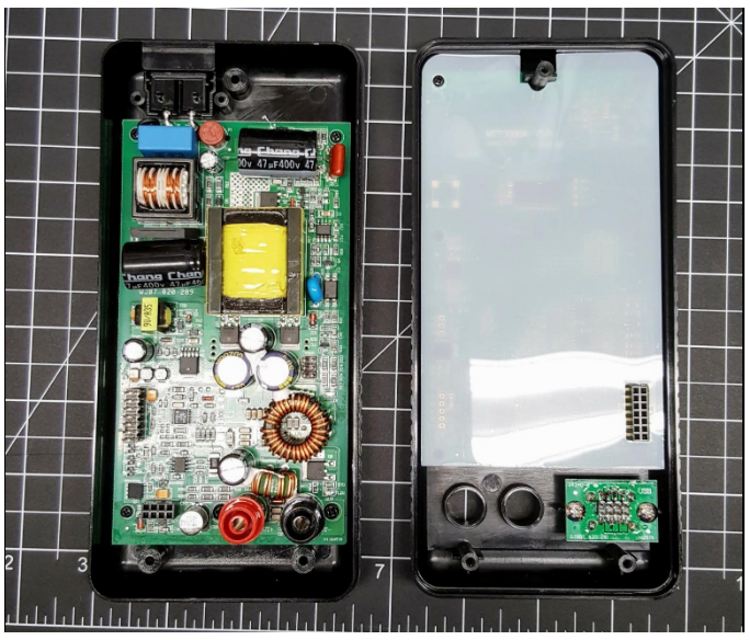
There are 2 PCBs:
- One attached to the top of the case has the display, buttons, jacks and the microcontroller
- One attached to the bottom of the case has the power supply circuits

Logic PCB
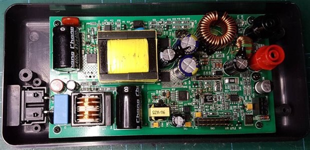
Power PCB
The unit uses an STM32F100 microcontroller for the control processor and there are pads to add a UART connector for communication. Someone attempted to interface the processor but was only able to get debug information from the serial port. I've attached the debug output. It appears that the power supply might be able to be controlled via the serial port which would be neat but it depends on how the firmware is implemented
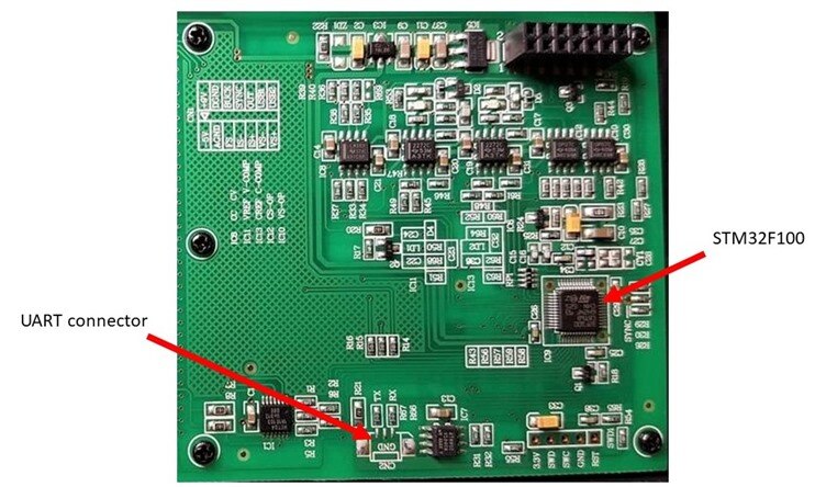
pcb markings: MPT3050A-V5.6 2015-08-06 QJB7.820.290 698580
sold as PS2002H or Tekpower TP3016M


On the PCB there is CN2 connector with pins: TX, GND, RX. It is a uart at 115200 bauds which
generates some debugging information from STM32F100 processor.
It does not respond to common AT commands, neither to any random characters transmitted over
uart, list of some received messages follows. If you will find out what protocol this device
uses, please let us know in comments section


power-on:
cm_test_mtz success
cm_read_user_zone success
cm_read_user_zone success
cm_read_user_zone success
c8 0 90 1 c8 0 2c 1 ff ff ff ff ff ff ff ff ff ff ff ff ff ff ff ff f6 24 0 0 94
2 24 0 43 29 0 0 4 55 d9 ff 3 26 0 0 dc 93 26 0 1f 28 0 0 57 13 d8 ff 5 2 55 5a
Power On Reset occurred....
RCC-CSR:0xc000002
core_init saved da v: 0.946200 235.995605
core_init saved ad v: 1.056300 -253.414001
core_init saved da c: 0.973100 252.822006
core_init saved ad c: 1.027100 -261.648895
core_init ref status:5a
brightness pwm:999
contrast pwm:160
leds active
lcd active
keyboard active
core active
meter active
dcdc active
screen active
dcdc work_mode
cvc active
gpio_usb_switch off
core_set_cv_dac_without_adjust: 0


output-enable:
awd:1011
core_output_key_handler


output-disable:
core_set_cv_dac_without_adjust: 0
core_output_key_handler


presets:
storage_read_cvc:0 200 300
storage_read_cvc:1 65535 65535
storage_read_cvc:2 65535 65535
storage_read_cvc:3 65535 65535
storage_read_cvc:4 65535 65535


change-of-value:
cm_write_user_zone success


brightness-change:
brightness pwm:0
brightness pwm:999


contrast-change:
contrast pwm:0
contrast pwm:80
contrast pwm:160
contrast pwm:240
contrast pwm:320
contrast pwm:500


toggle-usb-output:
gpio_usb_switch off
gpio_usb_switch off
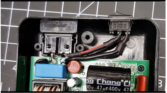
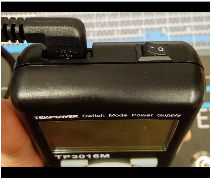
Power switch mod
One of the major gripes in reviews is the lack of a power switch and people have been adding a switch next to the power connector.