


While building my recent LoRaXes project I realized for successful battery power operation that I need a way to remove and restore power between data transmissions because the components that I was using did not have adequate sleep mode functionality. I found numerous references to projects using the TI TPL5110 Nano Power Switch to provide that functionality with Arduino compatible boards. Adafruit and Sparkfun both carry TPL5110 breakout boards. The Adafruit board is just a bit smaller and uses a trim pot to set the time duration while the Sparkfun board uses discrete resistors and a DIP switch. I'm using the Sparkfun board primarily because I could get it sooner.
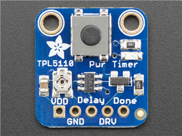
https://www.adafruit.com/product/3435

https://www.sparkfun.com/products/15353
Time interval testing
Sparkfun has a GitHub repository for their board: https://github.com/sparkfun/SparkFun_TPL5110_Nano_Power_Timer
The nano_power_timer_checker.ino program measures the time interval that output power is on if there is no done signal. Connect VDD (3.3V) and GND to the input of the TPL5110 and connect the VDD_OUT from the TPL5110 to an external interrupt on the MK WAN 1300 (also connect GND between boards). The MKR WAN 1300 is powered vis the microUSB connector. I had to modify the program slightly - it was using digital pin 3 for the interrupt input and that isn't an interrupt input on the MKR WAN 1300 so I used digital pin 0 instead. I also had to add a while(!Serial); statement to allow the Serial stream to start before outputting to the Serial Monitor.
/*
  Example Code for the TPL5110 Nano Power Switch Hookup Guide. This code
  checks to see the exact time that is set by the switched resistor. This time
  varies by the EXACT resistance of the resistor which has a 1% tolerance. In
  addition, the datasheet clarifies that each resistance has its own margin of
  error when producing the given time at a given resistance. What does this
  mean? If you are in need of HIGH precision timing, this may not be the choice
  for you. If you're looking to decrease power consumption to increase battery
  life in remote applications, applications that don't require high sampling
  rates (less than 100ms), or some Internet of Things application, then you're in the right
  place. If you're using a 3.3V microcontroller then use a 3.3V power source,
  if you're using a 5V microcontroller then use a 5V souce. Take care to not
  BURN OUT your digital I/O.
  SparkFun Electronics
  Date: May, 2019
  Author: Elias Santistevan
*/

/*  Hardware Setup on Redboard (Arduino):
   - VDD_OUT -> 0
   - GND -> GND
   - VDD -> 3.3V
*/

// REMEMBER - You must cycle power set new timer!
// ALSO - Press onboard button to begin cycle for long timers!
unsigned long endTimer = 0;
unsigned long beginTimer = 0;
float timerLength = 0;

bool start = false;
bool interrupted = false;
// VDD-OUT goes is on pinCheck
int pinCheck = 0;

void setup(){

  Serial.begin(115200);
  while(!Serial);
  Serial.println("Nano Power Switch - Timer Check!");
  Serial.println("Press the onboard button to begin the check.");
  pinMode(INPUT, pinCheck);
  // A interrupt may be overkill but it ensures we won't miss anything.
  attachInterrupt(digitalPinToInterrupt(pinCheck), checkTimer, FALLING);

}

void loop(){

  // Check that timer is on!
  if( (digitalRead(pinCheck) == HIGH) && (start == false)){
    Serial.print("Started: ");
    beginTimer = millis();
    Serial.println(beginTimer);
    start = true; // Power is high, first flag is set.
  }

  // If done signal is not sent back to Nano Power Switch, the Nano Power
  // Switch turns off power at the end of the timer anyway. After 50 ms the
  // Nano Power Switch will then turn the power back on. We're looking for that
  // small window when the power is turned off to calculate the exact time.
  // Code will enter this block when timer has started (Power from VDD_out is
  // ON) and when we've seen it go low (Power from VDD_OUT is off).
  if((interrupted == true) && (start == true)){
    Serial.print("Ended: ");
    Serial.println(endTimer);
    timerLength = endTimer - beginTimer; // Total time
    timerLength = timerLength + 50; // 50 ms off before back onto interval
    Serial.print("Timer Length: ");
    Serial.print(timerLength / 1000); // Convert to seconds...
    Serial.println("-------");
    Serial.println();
    interrupted = false;
    start = false;
  }

}

// When power is low, we get our endTimer value, and set the second flag.
void checkTimer(){
  endTimer = millis();
  interrupted = true;
}
Here is the output when the DIP switches are set for a 5 second delay:

The time indicated is minus the 50 milliseconds the timer takes to reset. It measures 4.7 seconds which is reasonably close.
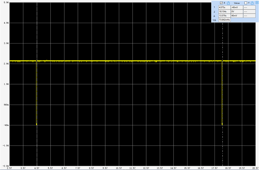
Here is a scope capture of the VDD_OUT pin:

Th scope measures 5.731 seconds - 50 milliseconds = 5.68 seconds (maybe a little less as the reset interval looks larger than 50 milliseconds - I should have set the cursors to measure only the positive duration). There is more time discrepancy than I would have expected.
Tried it again with a 13 second interval set:
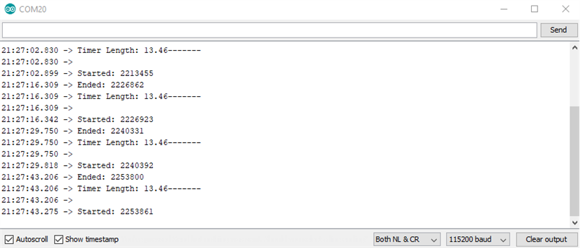
This time a closer match 13.45 vs 13.53 seconds. Not sure why the 2 measurements are off at 5 seconds, but that time difference won't matter in my application. I'll probably have the interval set between 1-5 minutes depending on which sensor I'm using.
Power cycling the MKR WAN 1300
To test the actual use case the VDD input of the TPL5110 is connected to the battery and the VDD_OUT is connected to the battery terminals of the MKR WAN 1300. Again, I needed to modify the sketch to accommodate the MKR WAN 1300 - the LED pin is digital pin 6 instead of 13 and I changed the done pin from digital pin 4 to 1 just for wiring convenience.
TPL5110_Blink_Done_Example.ino
All this sketch does on power up is toggle the LED on and off and then toggle the done_pin low and then high to signal the TPL5110 to turn off. The done_pin is connected to the Done input of the TPL5110.
/*
  TPL5110_Blink_Demo_example.ino

  Simple Example Code for the TPL5110 Nano Power Timer Hookup Guide. This code
  simply blinks the pin 6 LED and writes pin 1 (donePin pin) high. This shift from
  LOW to HIGH of the donePin pin, signals to the Nano Power Timer to turn off the
  microcontroller.
  SparkFun Electronics
  Date: May, 2019
  Author: Elias Santistevan
*/

int led = 6; // Pin 6 LED
int donePin = 1; // Done pin - can be any pin.

void setup(){

  pinMode(led, OUTPUT);
  pinMode(donePin, OUTPUT);

}

void loop(){
  // Blink.
  digitalWrite(led, HIGH);
  delay(1000);
  digitalWrite(led, LOW);
  delay(1000);

  // We're done!
  // It's important that the donePin is written LOW and THEN HIGH. This shift
  // from low to HIGH is how the Nano Power Timer knows to turn off the
  // microcontroller.
  digitalWrite(donePin, LOW);
  digitalWrite(donePin, HIGH);
  delay(10);
}
Here is a video demonstrating the operation.
The next step is to run this with the board connecting to the Things Network.
- Power up
- Connect to the Things Network
- Read the sensors
- Transmit the data
- Power down
To simplify the Things Network connection I will need to change the activation mode from Over the Air Activation (OTAA) to Activation by Personalization (ABP) and have the session keys stored in FRAM. That way the device does not have to negotiate session keys every time. I will have to initially connect via OTAA, however.
When I get this working I'll send the battery voltage data and do a life test on the batteries transmitting every 5 minutes. I also need to do a power measurement in power down mode. I'll need to disable the LED on the breakout board. The TPL5110 is spec'd at 35nA @ 2.5V. Not sure what it is at 3V. The Adafruit page indicated that it was measured to be 20uA ( I assume at 3.3V). That will be material for a follow-up blog.
Top Comments