


This time I am going to share with you an amazingly simple experience that is made possible using just an Arduino UNO board, a resistor and a capacitor. The RC circuit is a classic circuit in physics teaching and is composed by just a resistor R and a capacitor C in series. For details you can look at the Charging a Capacitor page of the HyperPhysics pages. Pupils study the charging and discharging of the capacitor when the circuit is connected to a battery. A rather simple mathematics gives the laws governing the process. It is easy to show that the voltage across the capacitor VC is a function of the time t: when the capacitor is not charged and is connected to a voltage V0 through the resistor, one gets
VC(t)=V0(1−e−tθ )
Here θ is a parameter having the dimensions of a time called the time constant of the circuit and is given by the product RC. When the capacitor is at its full charge and the two leads of the circuit are short circuited, the voltage across the capacitor drops with time with an exponential law whose time constant is still given by RC.
In the past, making the experience in a physics laboratory, was not so easy for students. The time constants that one can get using easily available components are short. For R of the order of few tens of kΩ and C of the order of few μF, the time constant is of the order of 10×103×10-6≈10-2s, i.e. a hundredth of a second. In order to measure the voltage across the capacitor as a function of time you need to connect the leads of a multimeter to the capacitor and read its value as a function of time, so you need time constants of the order, at least, of few seconds. That requires extremely large values of C (and R) that, of course, are not impossible to obtain, but are not so easy to find. Even in this case you can only collect few values.
With an Arduino board the job is greatly simplified and, needless to say, the precision you can attain with it is impressive.
The circuit, shown in the picture below (made with Fritzing), is easily realised connecting one of the leads of the resistor to the 5V pin of Arduino; the resistor is mounted in series with the capacitor that, in turn, has its second lead to the ground (GND). In order to measure the voltage across the capacitor, we connect the first lead of the capacitor to one of the Arduino analog inputs (A5).

Initially, the red wire is not connected to the 5V pin and the capacitor is not charged. Using the new Arduino IDE one can plot the values written to the Serial monitor as a function of time (in fact as a function of the reading). Consider the following code:
void loop() {
while (fabs(analogRead(A5)*5/1024. - lastReading) < 0.1) {
// do nothing
}
for (int i = 0; i < 480; i++) {
float currentReading = analogRead(A5)*5/1024.;
Serial.println(currentReading);
}
while (1) {
// do nothing
}
}
The first loop just waits until the current reading of the A5 pin (analogRead(A5)) differs from the value of lastReading for more than one tenth of a volt. The fabs function returns the absolute value of its argument. The reading of the analog input can be an integer number between 0 and 1024 representing a voltage ranging from 0 to 5 V. Multiplying the reading by 5 and dividing it by 1024 we then get the value of the voltage across the capacitor in Volts. Note the dot after 1024 that is needed to make the value a floating point number. If the dot is missing, both 5 and 1024 are represented as integers in the Arduino memory, as well as the value returned by analogRead(A5). This can lead to important consequences. Suppose, for example, that the analogRead(A5) function returns 123. Once multiplied by 5, we get 615 that, divided by 1024 gives just zero! In fact, 615/1024 is a ratio between two integers and the result is interpreted as an integer, too. Writing 615/1024. (with the dot after 1024) forces the CPU to represent the number 1024 as a floating point number and any operation made using an integer (615) and a floating point number (1024.) is a floating point number (about 0.6).
The value of lastReading must be set in the setup() of the Arduino sketch, in which we also initialise the Serial monitor with
Serial.begin(9600);
The first loop, then, is needed to start the program as well as the Serial plotter, having the time to connect the red wire to the 5V pin. Only when such a wire is connected to that pin the capacitor starts charging and the voltage across its leads starts raising. At this point we just read a fixed number of values of such a voltage (480 in our case) and write them on the Serial monitor. Each value written to the Serial monitor is shown on the Serial plotter versus time (in fact each value written to the Serial monitor is plotted against a sequential number, but in our case the readings are made at almost constant intervals of time, hence the horizontal axis values are proportional to time).
Once we read all the values we just stop doing anything with the last loop. The result is shown below.
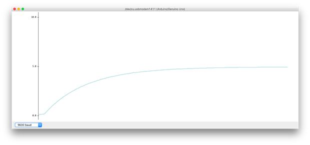
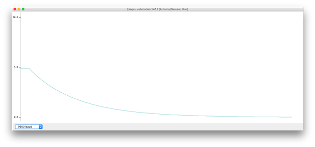
Such a very nice curve is exactly what we expected. You can even measure the discharge curve just repeating the experience in the following way: once charged, the capacitor remains charged until it is short circuited on the resistor. So, just disconnect the red wire from the 5V pin, restart the program and the Serial plotter, and connect the free lead of the red wire to the ground. The capacitor starts discharging on the resistor and the voltage across it changes. Soon after, the program makes 480 readings of the voltage and plot them, as can be seen below.
You can even be more quantitative with a slight change into the Arduino sketch. Consider the following:
float lastReading;
unsigned long time;
void setup() {
Serial.begin(9600);
lastReading = analogRead(A5)*5/1024.;
}
void loop() {
while (fabs(analogRead(A5)*5/1024. - lastReading) < 0.1) {
time = micros();
}
for (int i = 0; i < 480; i++) {
unsigned long now = micros();
Serial.print(now - time);
Serial.print(" ");
float currentReading = analogRead(A5)*5/1024.;
Serial.println(currentReading);
}
while (1) {
// do nothing
}
}
At the beginning of the loop we still wait for a change in the voltage, but in this case we collect the current time in the time variable. The current time is given by the micros() function returning the number of microseconds elapsed since the start of the sketch. As soon as the voltage changes we start measuring the voltages across the capacitor, but in this case we also get the time of each measurement and send to the Serial monitor both the time elapsed since the start of the measurements and the measurement values.
We write those two numbers to the Serial monitor, then copy and paste them into a text file for subsequent analysis. The picture below shows the data collected by us, during the charge:
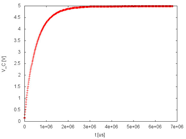
Times are in microseconds and you can see how rapid is the process. The capacitor is almost at its full charge already after 2 seconds. We used a resistor whose resistance was R=9.94 kΩ. We can then get the value of the capacitor from these measurements. With some mathematics one obtains a time constant θ of 0.53 s, from which we can derive C as θ/R≈54 μF. The nominal value of the capacitor we used is 47 μF. The error in the determination of it is then less than 15%.
Top Comments