


In the previous days I have built the code for all my clients (the light spots): they receive TCP commands from the Yún and control the lights accordingly.
1. The 3W RGB LED.
The first one is an Arduino Uno connected to a custom, constant-current RGB LED driver that can handle 3-10W LEDs (maybe even 20W). Here's a picture of it (yes, bad soldering job):

This has 3 PWM inputs which are connected to 3 pins on the Arduino. It gets 12V from any power supply which then also goes to the VIN pin on the Arduino, powering it.
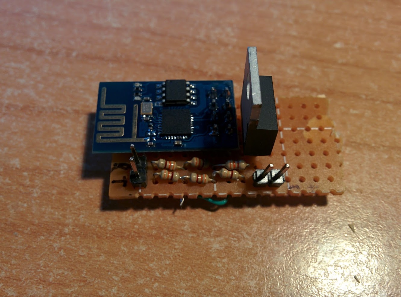
I then soldered an ESP8266 module on a protoboard, along with an LM1117 for bringing 5V down to 3.3V (the onboard regulator of the Arduino doesn't supply enough current) and a resistor circuit for level shifting.
Here it is:
Here is the full Arduino code that controls the lights: there is still some work to do but the main functions are there and working. It has EEPROM saving so that the last value is automatically retrieved at boot. I got the ESP8266 control code from a website then tweaked it, but it was a couple of months ago so I don't remember where.
// TCP STRING SYNTAX
// Manual Mode - M,COLOR_R,COLOR_G,COLOR_B$ (e.g. M,255,128,0$ for orange)
// Strobe Mode - S,DELAY$ (e.g. S,200$ for a random color every 200ms)
// Fade Mode - F,R_START,G_START,B_START,R_END,G_END,B_END,DELAY_TIME$ (e.g. F,255,0,0,0,0,255,5$ fades from red to blue waiting 5ms between every fade "step")
// Options (0 or 1) - TODO


#include <EEPROM.h>
#include <AltSoftSerial.h>


#define BUFFER_SIZE 30
#define SSID "TP-LINK"
#define PASSWORD "topolottolo"
#define PORT 8080


AltSoftSerial debugSerial;


enum {WIFI_ERROR_NONE=0, WIFI_ERROR_AT, WIFI_ERROR_RST, WIFI_ERROR_SSIDPWD, WIFI_ERROR_SERVER, WIFI_ERROR_UNKNOWN};


char dataIn[BUFFER_SIZE];
char dataOut[BUFFER_SIZE];
char buff[BUFFER_SIZE];
char options[2];
char *dataPtr = dataIn;
char *data2Ptr, *mode, *word1, *word2, *word3, *word4, *word5, *word6, *word7;


int addr = 0, index = 0, red = 6, green = 3, blue = 11, debugLED = 13, strSize = sizeof(dataIn);


boolean dataComplete = false, newData = false, first = false, wifi = false;


byte setupWiFi() {
  digitalWrite(debugLED, HIGH);


  // reset WiFi module
  Serial.println("AT+RST");
  delay(500);
  if(!Serial.find("ready")) {
  return WIFI_ERROR_RST;
  }


  // set mode 3
  //Serial.println("AT+CWMODE=3");
  delay(500);
  Serial.print("AT+CWJAP=\"");
  Serial.print(SSID);
  Serial.print("\",\"");
  Serial.print(PASSWORD);
  Serial.println("\"");
  delay(2000);
  if(!Serial.find("OK")) {
  return WIFI_ERROR_SSIDPWD;
  }
  delay(500);


  // start server
  Serial.println("AT+CIPMUX=1");
  if(!Serial.find("OK")){
  return WIFI_ERROR_SERVER;
  }
  delay(500);


  Serial.print("AT+CIPSERVER=1,"); // turn on TCP service
  Serial.println(PORT);
  if(!Serial.find("OK")){
  return WIFI_ERROR_SERVER;
  }
  delay(500);


  return WIFI_ERROR_NONE;
}


char* getIP() {
  Serial.println("AT+CIFSR");
    Serial.readBytesUntil('\r', buff, 20);
    Serial.readBytesUntil('\r', buff, 20);
    Serial.readBytesUntil('\r', buff, 20);


    return buff;
}


void setup() {
  Serial.begin(115200);
  debugSerial.begin(9600);
  pinMode(red, OUTPUT);
  pinMode(green, OUTPUT);
  pinMode(blue, OUTPUT);
  pinMode(debugLED, OUTPUT);
  EEPROMReadString(addr, dataIn);
  first = false;
  delay(1000);
  //wifi setup
  if(wifi = true){
    debugSerial.println("Enabling WiFi...");


  while (byte err = setupWiFi()) {
  digitalWrite(debugLED, LOW);


    // error
    debugSerial.print("Setup error:");
    debugSerial.println((int)err);
    debugSerial.println("Retrying...");
    }


    // connected
    debugSerial.print("Connected to AP!");
    // char *ip = getIP();
    // debugSerial.print(" IP address is: ");
    // debugSerial.println(ip);
  }

}


void loop() {

  while(Serial.available() > 0 && first == false && Serial.find(":")){
  if (dataComplete == true || newData == true){


  debugSerial.println("New data found! Erasing array...");


  //erase data array
  for (int i=0; i<sizeof(dataIn); i++){
  dataIn[i] = NULL;
  }


  //erase eeprom
  for (int i = 0; i < BUFFER_SIZE; i++){
    EEPROM.write(i, 0);
  }


  dataComplete = false;
  newData = false;
  }


  // if(wifi == false){


  // char character = Serial.read();
  // dataIn[index] = character;
  // index++;


  // if (character == '$'){
  // dataIn[index-1] = 0;
  // index = 0;
  // } //old serial input mode
  // }


  Serial.readBytesUntil('$', dataIn, BUFFER_SIZE);
  dataComplete = true;
  debugSerial.print("New data received: ");
  debugSerial.println(dataIn);
  EEPROMWriteString(addr, dataPtr);
  data2Ptr = strdup(dataIn);
  splitSerialString();
  }


  if(strcmp(mode, "M") == 0){
  setRGB(atoi(word1), atoi(word2), atoi(word3));
  if(first == true){
  first = false;
  }
  }


  if(strcmp(mode, "S") == 0){
  strobe(atoi(word1));
  if(first == true){
  first = false;
  }
  }


  if(strcmp(mode, "F") == 0){
  fade(atoi(word1), atoi(word2), atoi(word3), atoi(word4), atoi(word5), atoi(word6), atoi(word7));
  if(first == true){
  first = false;
  }
  }


  if(first == true){
  first = false;
  }
}


void setRGB(int r, int g, int b){
  analogWrite(red, r);
  analogWrite(green, g);
  analogWrite(blue, b);
}


void strobe(int timeDelay){
  long r, g, b;
    r = random(0, 256);
    g = random(0, 256);
    b = random(0, 256);
    analogWrite(red, r);
    analogWrite(green, g);
    analogWrite(blue, b);
    delay(timeDelay);
}


void fade(int rstart, int gstart, int bstart, int rend, int gend, int bend, int delayTime){
  int r = rstart;
  int g = gstart;
  int b = bstart;


  int rSteps = calcSteps(rstart, rend);
  int gSteps = calcSteps(gstart, gend);
  int bSteps = calcSteps(bstart, bend);


  int redVal = calcSign(rSteps);
  int greenVal = calcSign(gSteps);
  int blueVal = calcSign(bSteps);


  for(int i=1; i<=1020; i++){
  if(checkSerial() == true){
  setZero();
  break;
  }
  if(i % rSteps == 0){
  rstart+=redVal;
  if(rstart >= 0){
  analogWrite(red, rstart);
  }
  }
  if(i % gSteps == 0){
  gstart+=greenVal;
  if(gstart >= 0){
  analogWrite(green, gstart);
  }


  }
  if(i % bSteps == 0){
  bstart+=blueVal;
  if(bstart >= 0){
  analogWrite(blue, bstart);
  }
  }
  delay(delayTime);
  }


  float aux;
  aux=rstart;
  rstart=rend;
  rend=aux;
  aux=gstart;
  gstart=gend;
  gend=aux;
  aux=bstart;
  bstart=bend;
  bend=aux;


  redVal = -redVal;
  greenVal = -greenVal;
  blueVal = -blueVal;


  for(int i=1; i<=1020; i++){
  if(checkSerial() == true){
  setZero();
  break;
  }
  if(i % rSteps == 0){
  rstart+=redVal;
  if(rstart >= 0){
  analogWrite(red, rstart);
  }
  }
  if(i % gSteps == 0){
  gstart+=greenVal;
  if(gstart >= 0){
  analogWrite(green, gstart);
  }


  }
  if(i % bSteps == 0){
  bstart+=blueVal;
  if(bstart >= 0){
  analogWrite(blue, bstart);
  }
  }
  delay(delayTime);
  }
}


int calcSign(int steps){
  int val;
  if(steps > 0){
  val = 1;
  }
  else if(steps == 0){
  val = 0;
  }
  else{
  val = -1;
  }
  return val;
}


int calcSteps(int startValue, int stopValue){
  if(stopValue-startValue != 0){
  return 1020/(stopValue-startValue);
  }
  else{
  return 0;
  }
}


void EEPROMWriteString(int startAddr, const char *string){


  debugSerial.print("Writing data to EEPROM... ");


  for (int i = 0; i < BUFFER_SIZE; i++) {
    EEPROM.write(startAddr + i, string[i]);
    if(string[i]  != NULL)
    debugSerial.print(string[i]);

  }
  debugSerial.println("");
}


void EEPROMReadString(int addr, char* string){


  debugSerial.println("Reading data from EEPROM...");


  for(int i=0; i<BUFFER_SIZE; i++){


  char character = EEPROM.read(addr);
  string[i] = character;
  if(string[i]  != NULL)
  debugSerial.print(string[i]);
  addr++;


  }
  //Serial.println();
  addr = 0;
  dataComplete = true;
  splitSerialString();
}


void splitSerialString(){
  debugSerial.print("\nSplitting string...");
  data2Ptr = strdup(dataIn);
  mode = strtok(data2Ptr, ",");
  word1 = strtok(NULL, ",");
  word2 = strtok(NULL, ",");
  word3 = strtok(NULL, ",");
  word4 = strtok(NULL, ",");
  word5 = strtok(NULL, ",");
  word6 = strtok(NULL, ",");
  word7 = strtok(NULL, ",");
  debugSerial.println("done!");
  first = true;
}


boolean checkSerial(){
  if (Serial.available() > 0){
  newData = true;
  return true;
  }
}


void setZero(){
  analogWrite(red, 0);
  analogWrite(green, 0);
  analogWrite(blue, 0);
}
2. The Infineon shield + RGB strips.
I have also installed and configured the Infineon RGB shield.
I immediately noticed that there were no "shield headers" included... and I only had standard male headers, so I soldered them on.
I then had to connect the ESP8266 module to the RX and TX pins (as well as to 5V and GND) so I had to do this ugly hack:

Sure enough, the Infineon shield expressed its disappointment by self-bending its pins! :O

Everything is powered by an ATX breakout board (another nice summer project!).
One of the difficulties I encountered was converting 0-255 values into hex 0-4096 ones. Apart from that, the code is the same I posted a few lines before. This was my solution and it works, yet I'm not sure if I have done this right...
void setRGB(int r, int g, int b){
  //converts 0-255 values into i2c compatible values
  r = map(r, 0, 255, 0, 4095);
  g = map(g, 0, 255, 0, 4095);
  b = map(b, 0, 255, 0, 4095);
  char buffer[10];
  String red = String(r, HEX);
  String green = String(g, HEX);
  String blue = String(b, HEX);
  red = "0x" + red;
  green = "0x" + green;
  blue = "0x" + blue;
  red.toCharArray(buffer, 10);
  unsigned long r1 = strtoul(buffer, NULL, 16);
  green.toCharArray(buffer, 10);
  unsigned long g1 = strtoul(buffer, NULL, 16);
  blue.toCharArray(buffer, 10);
  unsigned long b1 = strtoul(buffer, NULL, 16);
  I2CWRITE6BYTES(ADDRESS, INTENSITY_RGB, r1, g1, b1);
}
Feels very redundant, maybe because I haven't fully understood int->hex conversions. Is there a better way of doing it apart from converting to strings?
I like the Infineon shield: it's packed of features and relatively easy to use, yet it seems to have this "hard-coded fade".
Right now, if I set the shield to be a single color (e.g. 255,0,0), the lights automatically fade from the previous color to red, according to the fade settings. I'm now working to integrate the fading in a better way with my web interface.
Thanks for reading! I will post a video in a few days, in the meanwhile I'm writing the review of the components!


