


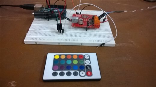
Hello Everyone, This is my third blog post for the Internet Of Holiday Lighting Road Test, in this post I will explain how did I managed to perform to change the color of RGB led strip with a simple IR Remote. Below is a picture of the setup :
Please watch the demo video it explains more than I can write about it...
HERE IS A DEMO VIDEO :
It is a very simple program, but first you will need to download this library : IRremote
once you do that everything is simple, just decode each button on your remote and make a case for each one of them.
the program simply reads the incoming hex code from your remote, and if the code match then the operation within the code is performed, in this code I have made it to change the color accordingly...
#include <IRremote.h>
#define SL_BD_RT 9600
#define RECV_PIN 7


#define RED 0XF720DF
#define GREEN 0XF7A05F
#define BLUE 0XF7609F
#define WHITE 0XF7E01F
#define CYAN 0XF7B04F
#define PINK 0XF76897
#define YELLOW 0XF728D7
#define ORANGE 0XF710EF
#define TEAL 0XF7A857
#define AQUA 0XF7906F
#define GOLD 0XF708F7
#define PURPLE 0XF748B7
#define OFF 0XF740BF


  #define ADDRESS                    0x15EUL

  #define INTENSITY_RED              0x11U
  #define INTENSITY_GREEN            0x12U
  #define INTENSITY_BLUE     0x13U
  #define INTENSITY_RGB              0x14U
  #define CURRENT_RED                0x21U
  #define CURRENT_GREEN              0x22U
  #define CURRENT_BLUE               0x23U
  #define CURRENT_RGB                0x24U
  #define OFFTIME_RED                0x41U
  #define OFFTIME_GREEN              0x42U
  #define OFFTIME_BLUE     0x43U
  #define WALKTIME                   0x50U
  #define DIMMINGLEVEL               0x60U
  #define FADERATE                   0x61U

  #define READ_INTENSITY_RED         0x81U
  #define READ_INTENSITY_GREEN       0x82U
  #define READ_INTENSITY_BLUE        0x83U
  #define READ_CURRENT_RED           0x84U
  #define READ_CURRENT_GREEN         0x85U
  #define READ_CURRENT_BLUE          0x86U
  #define READ_OFFTIME_RED           0x87U
  #define READ_OFFTIME_GREEN         0x88U
  #define READ_OFFTIME_BLUE          0x89U
  #define READ_WALKTIME              0x8AU
  #define READ_DIMMINGLEVEL          0x8BU
  #define READ_FADERATE              0x8CU


  #define SAVEPARAMETERS             0xA0U

  #define BCCUMODID                  0x50030008U
  #define CHIPID                     0x40010004U
  #define REDINTS                    0x500300A0U // BCCU_CH5
  #define REDINT                     0x500300A4U
  #define BLUEINTS                   0x50030078U
  #define STARTWALK                  0x50030018U

  #include <Wire.h>


  byte ledState;
  IRrecv irrecv(RECV_PIN);
  decode_results results;
  boolean power_state = LOW;

  unsigned int c[2] = {0};
  unsigned int d[4] = {0};
  unsigned int on = 0;
  unsigned int message = 0;
  unsigned long redcurr = 0;
  unsigned long greencurr = 0;
  unsigned long bluecurr = 0;
  unsigned long redoff = 0;
  unsigned long greenoff = 0;
  unsigned long blueoff = 0;
  unsigned long redint = 0x00;
  unsigned long greenint = 0x00;
  unsigned long blueint = 0x00;
  unsigned long fadetime = 0x00;
  unsigned long walk = 0x00;
  unsigned long brightness = 1;


void red(){
  I2CWRITE6BYTES (ADDRESS, INTENSITY_RGB, 0x0fff, 0x0, 0x0); // red
      delay(100);
  }
void green(){
   I2CWRITE6BYTES (ADDRESS, INTENSITY_RGB, 0x0, 0x0fff, 0x0); // red
      delay(100);
  }
void blue(){
   I2CWRITE6BYTES (ADDRESS, INTENSITY_RGB, 0x0, 0x0, 0x0fff); // red
      delay(100);
  }
void white(){
  I2CWRITE6BYTES (ADDRESS, INTENSITY_RGB, 0x0fff, 0x0fff, 0x0fff);
  delay(100);
  }
  void purple(){
  I2CWRITE6BYTES (ADDRESS, INTENSITY_RGB, 0x0fff, 0x0, 0x0fff);
  delay(100);
  }
  void yellow(){
  I2CWRITE6BYTES (ADDRESS, INTENSITY_RGB, 0x0fff, 0x0999, 0x0);
  delay(100);
  }
  void cyan(){
  I2CWRITE6BYTES (ADDRESS, INTENSITY_RGB, 0x0, 0x0fff, 0x0fff);
  delay(100);
  }
  void pink(){
  I2CWRITE6BYTES (ADDRESS, INTENSITY_RGB, 0x0fff, 0x0, 0x0888);
  delay(100);
  }
  void teal(){
  I2CWRITE6BYTES (ADDRESS, INTENSITY_RGB, 0x0, 0x0fff, 0x0888);
  delay(100);
  }
  void off(){
  I2CWRITE6BYTES (ADDRESS, INTENSITY_RGB, 0x0, 0x0, 0x0);
  delay(100);
  }
  void orange(){
  I2CWRITE6BYTES (ADDRESS, INTENSITY_RGB, 0x0fff, 0x0333, 0x0);
  delay(100);
  }
  void aqua(){
  I2CWRITE6BYTES (ADDRESS, INTENSITY_RGB, 0x0, 0x0999, 0x0fff);
  delay(100);
  }

void setup() {


    Serial.begin(SL_BD_RT);
    Wire.begin();
    irrecv.enableIRIn();

    while (on != 1) // Wait for shield to respond, keep setting the values till it does
    {
      I2CWRITE2BYTES (ADDRESS, FADERATE, 0x0000); // Immediate fade
      I2CWRITE2BYTES (ADDRESS, DIMMINGLEVEL, 0x0000); // 0% brightness level
      on = I2CREAD(ADDRESS, READ_DIMMINGLEVEL); // Request for brightness level
      if (message == 1 && on == 0) // If message received and dimming level = 0%, "message" is set in the I2CREAD function
      {
        message = 0;
        on = 1; // break out of loop
      }

    }

    // now we will chane the values again and wait till there being red back
    while (redcurr != 0x15 || greencurr != 0x15 || bluecurr != 0x15 || redoff != 0x38 || greenoff != 0x39 || blueoff != 0x38 || brightness != 0)
    {
        I2CWRITE6BYTES (ADDRESS, INTENSITY_RGB, 0x0000, 0x000, 0x0000); // Off Light
  // Ensure that parameters are set up correctly. Read back and check. If wrong, write and read again.
        redcurr = I2CREAD (ADDRESS, READ_CURRENT_RED); // Read the red current intensity
  greencurr = I2CREAD (ADDRESS, READ_CURRENT_GREEN); // Read the green current intensity
  bluecurr = I2CREAD (ADDRESS, READ_CURRENT_BLUE); // Read the blue current intensity
  redoff = I2CREAD (ADDRESS, READ_OFFTIME_RED); // Read the off-time of the red channel
  greenoff = I2CREAD (ADDRESS, READ_OFFTIME_GREEN); // Read the off-time of the green channel
  blueoff = I2CREAD (ADDRESS, READ_OFFTIME_BLUE); // Read the off-time of the blue channel
  brightness = I2CREAD (ADDRESS, READ_DIMMINGLEVEL); // Read the dimming level

        I2CWRITE2BYTES (ADDRESS, OFFTIME_RED, 0x38); // Set off-time of red channel to 0x38
  I2CWRITE2BYTES (ADDRESS, OFFTIME_GREEN, 0x39); // Set off-time of green channel to 0x39
  I2CWRITE2BYTES (ADDRESS, OFFTIME_BLUE, 0x38); // Set off-time of blue channel to 0x38
  I2CWRITE2BYTES (ADDRESS, CURRENT_RED, 0x15); // Set current intensity of red channel to 0x15
  I2CWRITE2BYTES (ADDRESS, CURRENT_GREEN, 0x15); // Set current intensity of green channel to 0x15
  I2CWRITE2BYTES (ADDRESS, CURRENT_BLUE, 0x15); // Set current intensity of blue channel to 0x15
  I2CWRITE2BYTES (ADDRESS, DIMMINGLEVEL, 0x0000); // LEDs all off as any intensity * 0 will = 0

    }

    delay(100); // OK, so were getting response from the infineon so read back values from slave and print them
    Serial.print("Red Int: ");     redint = I2CREAD (ADDRESS, READ_INTENSITY_RED); // request from shield red colour intensity
    Serial.print("Green Int: ");   greenint = I2CREAD (ADDRESS, READ_INTENSITY_GREEN); // request from shield green colour intensity
    Serial.print("Blue Int: ");    blueint = I2CREAD (ADDRESS, READ_INTENSITY_BLUE); // request from shield blue colour intensity
    Serial.print("Red Curr: ");    redcurr = I2CREAD (ADDRESS, READ_CURRENT_RED); // request from shield peak current reference of red channel
    Serial.print("Green Curr ");   greencurr = I2CREAD (ADDRESS, READ_CURRENT_GREEN); // request from shield peak current reference of green channel
    Serial.print("Blue Curr: ");   bluecurr = I2CREAD (ADDRESS, READ_CURRENT_BLUE); // request from shield peak current reference of blue channel
    Serial.print("Red PWM: ");     redoff = I2CREAD (ADDRESS, READ_OFFTIME_RED); // request from shield off-time of red channel
    Serial.print("Green PWM: ");   greenoff = I2CREAD (ADDRESS, READ_OFFTIME_GREEN); // request from shield off-time of green channel
    Serial.print("Blue PWM: ");    blueoff = I2CREAD (ADDRESS, READ_OFFTIME_BLUE); // request from shield off-time of blue channel
    Serial.print("Walk: ");        walk = I2CREAD (ADDRESS, READ_WALKTIME); // request from shield walk-time
    Serial.print("Brightness: ");  brightness = I2CREAD (ADDRESS, READ_DIMMINGLEVEL); // request from shield brightness level
    Serial.print("FadeTime: ");    fadetime = I2CREAD (ADDRESS, READ_FADERATE); // request from shield fade rate

    // now setup for test

    I2CWRITE2BYTES (ADDRESS, OFFTIME_RED, 0x38); // Set off-time of red channel to 0x38
    I2CWRITE2BYTES (ADDRESS, OFFTIME_GREEN, 0x39); // Set off-time of green channel to 0x39
    I2CWRITE2BYTES (ADDRESS, OFFTIME_BLUE, 0x38); // Set off-time of blue channel to 0x38
    I2CWRITE6BYTES (ADDRESS, CURRENT_RGB, 0x80, 0x80, 0x80); // Set current of red channel to 0x80 = 780mA
    I2CWRITE2BYTES (ADDRESS, FADERATE, 0x0000); // Fade Rate between intensities --> 0.0s
    I2CWRITE2BYTES (ADDRESS, WALKTIME, 0x0000); // walk time between colors = 0s
    I2CWRITE6BYTES (ADDRESS, INTENSITY_RGB, 0x0555, 0x0555, 0x0555); // low level White Light
    I2CWRITE2BYTES (ADDRESS, DIMMINGLEVEL, 0x0FFF); // Maximum dimming level means inensity settings are directly used
    I2CWRITE6BYTES (ADDRESS, INTENSITY_RGB, 0x0, 0x0, 0x0);


}

  // the loop routine runs over and over again forever:
void loop() {
if (irrecv.decode(&results)) {  //If IR receive results are detected
    Serial.println(results.value, HEX);
    switch (results.value) {

    case RED:
         red();
    break;


    case BLUE:
         blue();
    break;


    case GREEN:
         green();
    break;


   case WHITE:
          white();
    break;

    case CYAN:
          cyan();
    break;

    case YELLOW:
          yellow();
    break;

    case PURPLE:
          purple();
    break;

    case AQUA:
          aqua();
    break;

    case OFF:
          off();
    break;

    case ORANGE:
          orange();
    break;

    case PINK:
          pink();
    break;

    case TEAL:
          teal();
    break;


    default:
       Serial.println("");
  }


    delay(20);  // 1/5 second delay for arbitrary clicks.  Will implement debounce later.
    irrecv.resume(); // Receive the next value
  }

}


// Infineon functions follow
/*
  Parameters (IN): int Address - Address of RGB LED Shield, Default 0x15E
                   int Command - Defined I2C Commands i.e. INTENSITY_RED, INTENSITY_GREEN, INTENSITY_BLUE
                   unsigned int Data - 16bit data to be written to slave
  Parameters (OUT): None
  Return Value: None
  Description: This function will write 2 bytes of word to the I2C bus line
  */

  void I2CWRITE2BYTES (int Address, int Command, unsigned int Data)
  {
    unsigned int upperByte, lowerByte; // Separate 4 byte data into 2 byte values
    lowerByte = Data;
    upperByte = Data >> 8;

    unsigned int lowerSLAD = (unsigned int) (Address & 0x00FF); // Putting address into correct format
    unsigned int upperSLAD = Address >> 8;
    upperSLAD |= 0x79; // First 5 bits 11110 and last bit '1' for a write

    Wire.beginTransmission(byte(upperSLAD)); // Start I2C transmission
    Wire.write(byte(lowerSLAD)); // address lower 8 bits of i2c address
    Wire.write(byte(Command)); // write command
    Wire.write(byte(upperByte)); // write data
    Wire.write(byte(lowerByte));
    Wire.endTransmission(true);

  }
   /*
  Parameters (IN): int Address - Address of RGB LED Shield, Default 0x15E
                   int Command - Defined I2C Commands i.e. INTENSITY_RGB, CURRENT_RGB
                   unsigned int DataOne, unsigned int DataTwo, unsigned int DataThree - Three 16bit data to be written to slave
  Parameters (OUT): None
  Return Value: None
  Description: This function will write 6 bytes of word to the I2C bus line
  */

  void I2CWRITE6BYTES (unsigned int Address, unsigned int Command, unsigned int DataOne, unsigned int DataTwo, unsigned int DataThree) // DataOne: Red, DataTwo: Green, DataThree: Blue
  {
    unsigned int upperByte, lowerByte; // Split each Data parameter into upper and lower 8 bytes because I2C format sends 8 bytes of data each time
    lowerByte = DataOne;
    upperByte = DataOne >> 8;

    unsigned int lowerSLAD = (unsigned int) (Address & 0x00FF);
    unsigned int upperSLAD = Address >> 8;
    upperSLAD |= 0x79; // First 5 bits 11110 and last bit '1' for a write

    Wire.beginTransmission(byte(upperSLAD)); // Red
    Wire.write(byte(lowerSLAD));
    Wire.write(byte(Command));
    Wire.write(byte(upperByte));
    Wire.write(byte(lowerByte));
    lowerByte = DataTwo;
    upperByte = DataTwo >> 8;
    Wire.write(byte(upperByte));
    Wire.write(byte(lowerByte));
    lowerByte = DataThree;
    upperByte = DataThree >> 8;
    Wire.write(byte(upperByte));
    Wire.write(byte(lowerByte));
    Wire.endTransmission(true);

  }

/*
  Parameters (IN): int Address - Address of RGB LED Shield, Default 0x15E
                   int Command - Defined I2C Commands i.e. DMX16Bit
                   unsigned int DataOne, unsigned int DataTwo, unsigned int DataThree, usigned int DataFour, unsigned int DataFive - Three 16bit data to be written to slave
  Parameters (OUT): None
  Return Value: None
  Description: This function will write 12 bytes of word to the I2C bus line
  */

  void I2CWRITE12BYTES (unsigned int Address, unsigned int Command, unsigned int DataOne, unsigned int DataTwo, unsigned int DataThree, unsigned int DataFour, unsigned int DataFive, unsigned int DataSix) // DataOne: Red, DataTwo: Green, DataThree: Blue
  {
    unsigned int upperByte, lowerByte;
    lowerByte = DataOne;
    upperByte = DataOne >> 8;

    unsigned int lowerSLAD = (unsigned int) (Address & 0x00FF);
    unsigned int upperSLAD = Address >> 8;
    upperSLAD |= 0x79; // First 5 bits 11110 and last bit '1' for a write

    Wire.beginTransmission(byte(upperSLAD));
    Wire.write(byte(lowerSLAD));
    Wire.write(byte(Command)); // write command
    Wire.write(byte(upperByte)); // write 2 bytes
    Wire.write(byte(lowerByte));

    lowerByte = DataTwo;
    upperByte = DataTwo >> 8;
    Wire.write(byte(upperByte)); // write next two bytes
    Wire.write(byte(lowerByte));

    lowerByte = DataThree;
    upperByte = DataThree >> 8;
    Wire.write(byte(upperByte));
    Wire.write(byte(lowerByte));


    lowerByte = DataFour;
    upperByte = DataFour >> 8;
    Wire.write(byte(upperByte));
    Wire.write(byte(lowerByte));


    lowerByte = DataFive;
    upperByte = DataFive >> 8;
    Wire.write(byte(upperByte));
    Wire.write(byte(lowerByte));


    lowerByte = DataSix;
    upperByte = DataSix >> 8;
    Wire.write(byte(upperByte));
    Wire.write(byte(lowerByte));
    Wire.endTransmission(true);

  }

   /*
  Parameters (IN): int Address - Address of RGB LED Shield, Default 0x15E
                   int Command - Defined read I2C Commands i.e. READ_INTENSITY_RED, READ_INTENSITY_GREEN, READ_INTENSITY_BLUE
  Parameters (OUT): None
  Return Value: Requested data from Shield will be sent back
  Description: This function will request 2 bytes of word from the shield
  */

  unsigned int I2CREAD (unsigned int Address, unsigned int Command) // Returns data sent by slave
  {
    int i = 0;
    unsigned int lowerSLAD = (unsigned int) (Address & 0x00FF);
    unsigned int upperSLAD = Address >> 8;
    upperSLAD |= 0x79;

    Wire.beginTransmission(byte(upperSLAD)); // Red
    Wire.write(byte(lowerSLAD));
    Wire.write(byte(Command));
    Wire.endTransmission(false); // false for Repeated Start

    Wire.beginTransmission(byte(upperSLAD));
    Wire.write(byte(lowerSLAD));
    Wire.requestFrom(upperSLAD, 2, true);
    unsigned int data = 0;

    while(Wire.available())    // slave may send less than requested. Print out received data byte
    {
      message = 1;
      c[i] = Wire.read(); // receive a byte as character
      i++;

    }
    Wire.endTransmission(true);

    data = c[1]; // write data to serial monitor. c[1] is higher byte
    data = (data << 8) | c[0];  // shift left and combine with lower byte
    Serial.print("0x");
    if (data < 0x1000)
        Serial.print("0");
    Serial.println(data, HEX);
    return data;
  }

   /*
  Parameters (IN): int Address - Address of RGB LED Shield, Default 0x15E
                   int Command - DIRECTACCESS_READ
  Parameters (OUT): None
  Return Value: Requested data from the Shield will be returned
  Description: This function will request 4 bytes of data from shield.
  */

unsigned long I2CREAD_DIRECTACCESS (unsigned int Address, unsigned int Command, unsigned long registerAddress)
  {
    int i = 0;
    unsigned int lowerSLAD = (unsigned int) (Address & 0x00FF); // sending command + address
    unsigned int upperSLAD = Address >> 8;
    upperSLAD |= 0x79; // First 5 bits 11110 and last bit '1' for a write

    Wire.beginTransmission(byte(upperSLAD));
    Wire.write(byte(lowerSLAD));
    Wire.write(byte(Command));

    unsigned int firstByte, secondByte, thirdByte, fourthByte;
    firstByte = registerAddress >> 24; // top byte
    secondByte = registerAddress >> 16;
    thirdByte = registerAddress >> 8;
    fourthByte = registerAddress; // bottom byte

    Wire.write(byte(firstByte));
    Wire.write(byte(secondByte));
    Wire.write(byte(thirdByte));
    Wire.write(byte(fourthByte));

    Wire.endTransmission(false); // false for Repeated Start

    Wire.beginTransmission(byte(upperSLAD)); // request for read
    Wire.write(byte(lowerSLAD));
    Wire.requestFrom(upperSLAD, 4, true);
    unsigned long data = 0;

    while(Wire.available())    // slave may send less than requested. Print out received data byte
    {
      d[i] = 0;
      d[i] = Wire.read(); // receive a byte as character
      i++;
    }


    Wire.endTransmission(true);

    data = d[3]; // combining into one variable. Highest byte received first
    data = (data << 8) | d[2];
    data = (data << 8) | d[1];
    data = (data << 8) | d[0];
    Serial.print("0x");
    if (data < 0x10000000)
        Serial.print("0");
    Serial.println(data, HEX);
    return data;
  }
   /*
  Parameters (IN): int Address - Address of RGB LED Shield, Default 0x15E
                   int Command - Defined I2C Commands i.e. DIRECTACCESS_OR, DIRECTACCESS_AND, DIRECTACCESS_MOVE
                   unsigned long registerAddress - address of target register
                   unsigned long Data - 32 bits data to be written to register
  Parameters (OUT): None
  Return Value: None
  Description: This function will write 4 bytes of data to specified register
  */
  void I2CWRITE_DIRECTACCESS (unsigned int Address, unsigned int Command, unsigned long registerAddress, unsigned long Data) // For accessing registers directly
  {
    int i = 0;
    unsigned int lowerSLAD = (unsigned int) (Address & 0x00FF); // sending command + address
    unsigned int upperSLAD = Address >> 8;
    upperSLAD |= 0x79; // First 5 bits 11110 and last bit '1' for a write

    Wire.beginTransmission(byte(upperSLAD));
    Wire.write(byte(lowerSLAD));
    Wire.write(byte(Command));

    unsigned int firstByte, secondByte, thirdByte, fourthByte; // Send address of register first
    firstByte = registerAddress >> 24; // top byte
    secondByte = registerAddress >> 16;
    thirdByte = registerAddress >> 8;
    fourthByte = registerAddress; // bottom byte

    Wire.write(byte(firstByte));
    Wire.write(byte(secondByte));
    Wire.write(byte(thirdByte));
    Wire.write(byte(fourthByte));

    firstByte = Data >> 24; // top byte
    secondByte = Data >> 16;
    thirdByte = Data >> 8;
    fourthByte = Data; // bottom byte


    Wire.write(byte(firstByte)); // send 4 bytes of data
    Wire.write(byte(secondByte));
    Wire.write(byte(thirdByte));
    Wire.write(byte(fourthByte));
    Wire.endTransmission(true);

  }
   /*
  Parameters (IN): int Address - Address of RGB LED Shield, Default 0x15E
                   unsigned int newAddress - Address the shield should change to
  Parameters (OUT): None
  Return Value: None
  Description: This function will change the I2C address of the slave
  */

  void CHANGEADDRESS (unsigned int Address, unsigned int newAddress)
  {
    unsigned int lowerSLAD = (unsigned int) (Address & 0x00FF);
    unsigned int upperSLAD = Address >> 8;
    upperSLAD |= 0x79; // First 5 bits 11110 and last bit '1' for a write

    Wire.beginTransmission(byte(upperSLAD)); // Red
    Wire.write(byte(lowerSLAD));
    Wire.write(byte(0x70)); // Command to change address
    lowerSLAD = (unsigned int) (newAddress & 0x00FF);
    upperSLAD = newAddress >> 7; // Split address into 2 bytes
    upperSLAD |= 0xF0; // 10 bit addressing: First 5 bits have to be 11110.
    upperSLAD &= 0xFE;
    Wire.write(byte(upperSLAD));
    Wire.write(byte(lowerSLAD));
    Wire.endTransmission(true);
  }

   /*
  Parameters (IN): int Address - Address of RGB LED Shield, Default 0x15E
                   unsigned int Command - DMXON, DMXOFF
  Parameters (OUT): None
  Return Value: None
  Description: This function will enable or disable DMX512 control on shield
  */

  void I2CDMX (unsigned int Address, unsigned int Command) // Switch off / on the DMX
  {
    unsigned int lowerSLAD = (unsigned int) (Address & 0x00FF); // Putting address into correct format
    unsigned int upperSLAD = Address >> 8;
    upperSLAD |= 0x79;

    Wire.beginTransmission(byte(upperSLAD)); // Start I2C transmission
    Wire.write(byte(lowerSLAD));
    Wire.write(byte(Command));
    Wire.endTransmission(true);

  }
   /*
  Parameters (IN): int Address - Address of RGB LED Shield, Default 0x15E
  Parameters (OUT): None
  Return Value: None
  Description: This function will request the shield to save configurations to flash memory
  */

  void I2CSAVEPARAM (unsigned int Address)
  {
    int i = 0;
    unsigned int lowerSLAD = (unsigned int) (Address & 0x00FF);
    unsigned int upperSLAD = Address >> 8;
    upperSLAD |= 0x79;

    Wire.beginTransmission(byte(upperSLAD));
    Wire.write(byte(lowerSLAD));
    Wire.write(byte(SAVEPARAMETERS)); // write SAVEPARAMETERS command
    Wire.endTransmission(false); // false for Repeated Start

    Wire.beginTransmission(byte(upperSLAD));
    Wire.write(byte(lowerSLAD)); // write to address lower 8 bits of slave address
    Wire.requestFrom(upperSLAD, 2, true);  // send READ request with upper slave address
    unsigned int data = 0;

    while(Wire.available())    // slave may send less than requested. Print out received data byte
    {
      message = 1;
      c[i] = Wire.read(); // receive a byte as character
      i++;
    }
    Wire.endTransmission(true); // STOP condition

    data = c[1]; // print the data on serial monitor
    data = (data << 8) | c[0];
    Serial.print("0x");
    if (data < 0x1000)
        Serial.print("0");
    Serial.println(data, HEX);

  }
In my next blog post i will write about my final "True IoT" method for my smart phone lighting project....
I know this this post is not related to smartphone lighting, but as I wrote it in my application for this roadtest, so i did it...