


My entry for the Internet of Holiday Lights is an electro-mechanical wreath.
My first blog post was a brain dump of possibilities.
In my second post I made a paper prototype.
My third post was about getting the Arduino Yun up and running.
In the fourth post I used the Linux part of the Yun to get at the current date and time.
In the fifth post I scavenged a stepper motor from a flatbed scanner.
I have that motor working now.
The motor driver kit
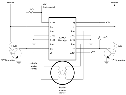
In my previous post I blogged about driving the motor with a 4 transistor H-bridge, and how I goofed that up. So I ended up dragging home a Velleman MOTOR & POWER SHIELD VOOR ARDUINO.
That shield's design is very similar to the Arduino Circuit for Bipolar Stepper Motor (the two pins example). Here's the two schematics side by side:

Velleman and myself have one particular thing in common. We're both from Belgium.
The last time I've built a kit from them must have been somewhere in the late 80's. So I was quite excited to spend an evening of my Christmas holidays building up the kit.
There was one unpleasant thingy though. The smd ic was packaged in bubble wrap with tape around it. And someone in the kit assembly department must have been too strong for that job:
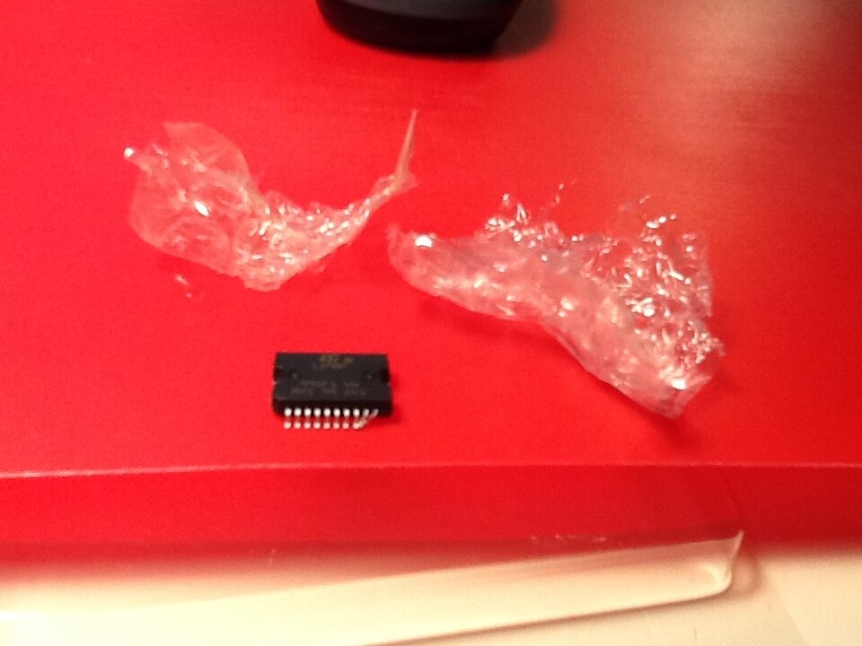
No real harm done, I could straighten the pins without too much effort. Still, I'm expecting better...
Building the kit
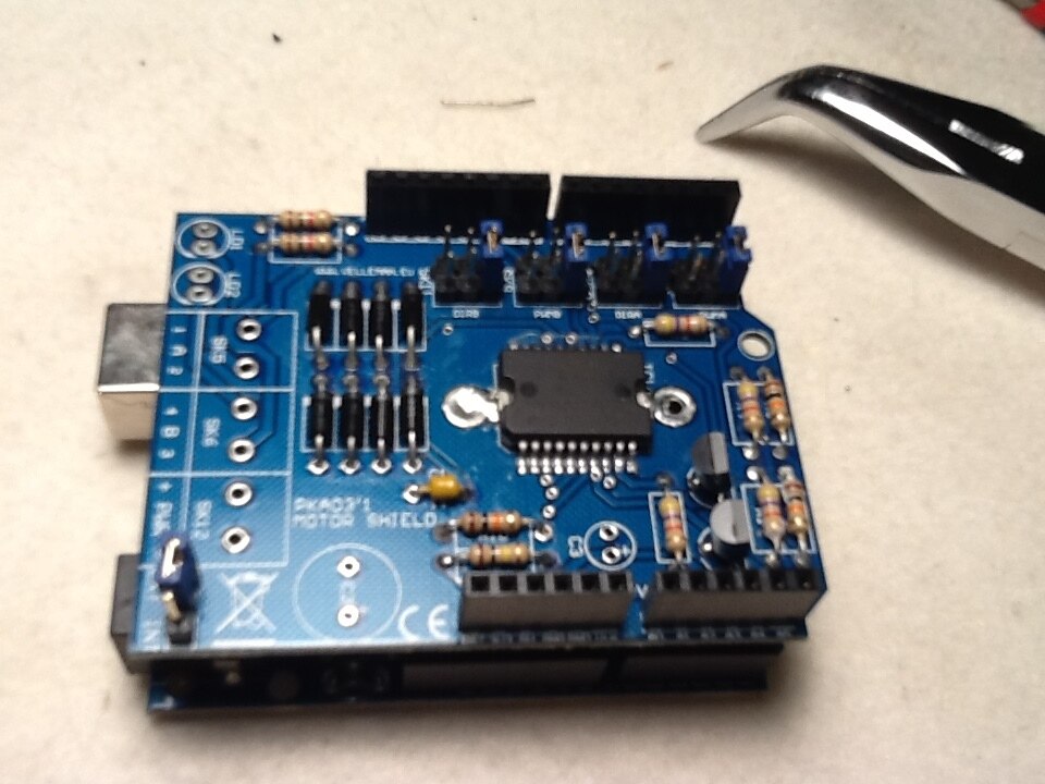
That was not too difficult. There's only one smd component. In stead of soldering it with a fine tip pin by pin at the end - as advised by Velleman - I put that one up first.
I used solder paste and hot air. At my age, your eyes are happy that the don't have to stare at the 20 tiny pins while hand soldering each of them.
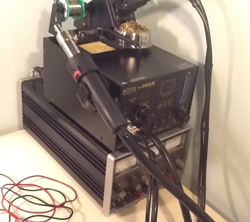
| solder station |
|---|
My solder station is an Aoyue 968A+. I've bought that with a voucher my company gave me earlier this year as a present. Because I'm a cheapskate, I searched for the lowest price (shipping included). That was on Amazon America. The pleasant surprise came a week later when the Belgian tax authorities charged me an import tax that was lifting it way up above buying local. Go figure.
I'm rather fond on that solder station. Works well for me. |
The other thing that I did different than Velleman's instructions is using flux. I'm soldering lead-free, and flux is more than welcome in that situation.
The kit is complete, and the instructions are easy to follow. And since it's been a while since I did that, it was quite an entertaining exercise.
The software
I want to use the Arduino Stepper library. In this contest, one of my goals is to stick close to the nature of the devices.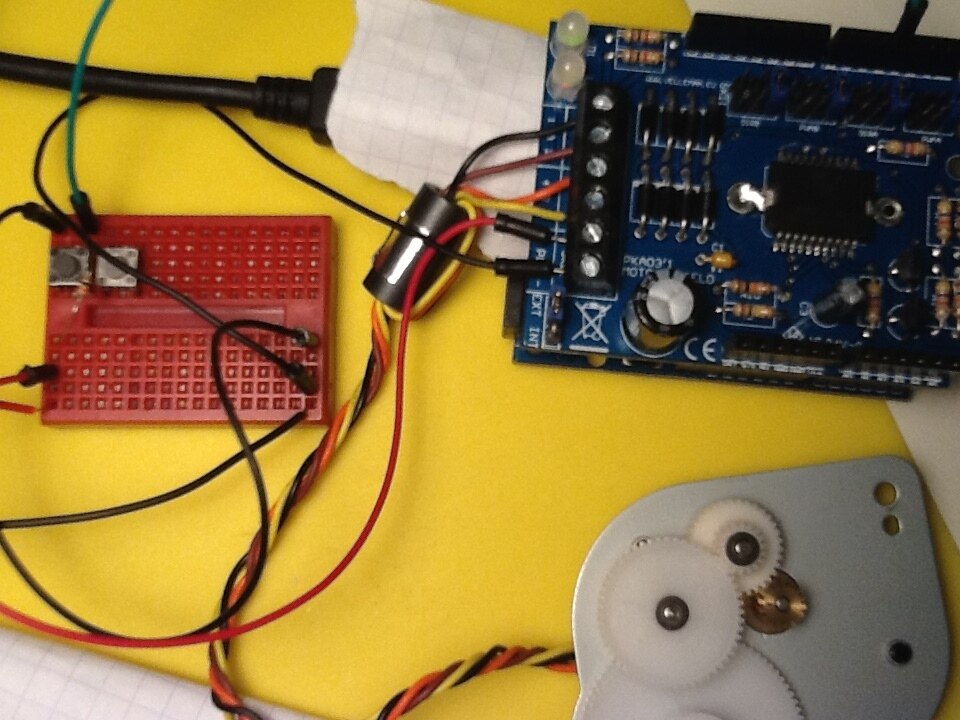
Since there isn't too much difference in design between Velleman's kit and Arduino's example, it shouldn't be too hard. And it isn't.
For the moment, I've left all the jumpers on my kit in their default position.
- enable coil A on digital3
- direction coil A on digital 2
- enable coil B on digital 9
- direction coil B on digital 8
I could use the Ardiono Shield example libraries with these changes:
in the constructor and setup(), I switched the output pins to reflect the jumpers on my shield, and enabled the enable (sic) pins.
#define STEPA 2
#define STEPB 8
#define ENAA 3
#define ENAB 9
#define BUTTON_CTRL 4
// ...
Stepper myStepper(stepsPerRevolution, STEPA, STEPB);


void setup() {
  pinMode(ENAA, OUTPUT);  //Set control pins to be outputs
  pinMode(ENAB, OUTPUT);
  digitalWrite(ENAA, LOW);
  digitalWrite(ENAB, LOW);
// ...
// set the speed at 60 rpm:
  myStepper.setSpeed(60);
   // initialize the serial port:
  Serial.begin(9600);

// ...
in the loop(), I took advantage of the enable capability of my shield:
void loop() {
  // step one revolution  in one direction:
// ...
    Serial.println("clockwise");

    digitalWrite(ENAA, HIGH);
    digitalWrite(ENAB, HIGH);
    myStepper.step(100*stepsPerGearRevolution);  //  yes, I'm testing 100 full turns of the slowest wheel in my gearbox top test the resolution :) -- too lazy to count the cogs and ratios in my gearbox
    digitalWrite(ENAA, LOW);
    digitalWrite(ENAB, LOW);
    delay(500);
  }
I've successfuly tested the following examples on my stepper motor / shield combination:
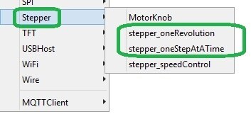
I haven't tried the other Stepper examples. I have no reason why they shouldn't work too.
Motor and gearbox resolution
I've measured the motor resolution by adapting the stepper_oneRevolution example.
I found info on my motor (the Neocene 2T3542146) on the manufacturer's site. The step angle is 3,75°. 3,75°per Step = 96 steps per rotation.
I have verified that by running this adapted example:
#include <Stepper.h>


const int stepsPerRevolution = 96;  // change this to fit the number of steps per revolution
// for your motor


// initialize the stepper library on pins 8 through 11:
Stepper myStepper(stepsPerRevolution, 8, 2);


int stepCount = 0;         // number of steps the motor has taken


void setup() {
  // initialize the serial port:
  Serial.begin(9600);
  pinMode(3, OUTPUT);  //Set control pins to be outputs
  pinMode(9, OUTPUT);
  digitalWrite(3, HIGH);
  digitalWrite(9, HIGH);

}


void loop() {
  // step one step:
  myStepper.step(1);
  Serial.print("steps:" );
  Serial.println(stepCount);
  stepCount++;
  delay(25);
}
To measure the full resolution, I marked one cog of the slowest gear in the reduction. Then I activated the motor and counted how many rotations of the motor where needed for one full rotation of that last gear in the reduction.
I came at approx 29.5 rotations.
Then I made the following sketch to fine tune. It waits for a button press and then takes what I think are the right amount of steps to make the slowest gear go around 100 times.
That should give me enough resolution to survive the advent weeks.
/*
Stepper Motor Control - one revolution


This program drives a unipolar or bipolar stepper motor.
The motor is attached to digital pins 8 - 11 of the Arduino.


The motor should revolve one revolution in one direction, then
one revolution in the other direction.


Created 11 Mar. 2007
Modified 30 Nov. 2009
by Tom Igoe  (adapted by jc for the Internet of Holiday Lights - Velleman KA03 motor driver with Neocene 2T3542xmotor


*/


#include <Stepper.h>


#define STEPA 2
#define STEPB 8
#define ENAA 3
#define ENAB 9
#define BUTTON_CTRL 4


const int stepsPerRevolution = 96;


const int stepsPerGearRevolution = 30*stepsPerRevolution-32;  // change this to fit the number of steps per revolution


Stepper myStepper(stepsPerRevolution, STEPA, STEPB);


void setup() {
  pinMode(ENAA, OUTPUT);  //Set control pins to be outputs
  pinMode(ENAB, OUTPUT);
  digitalWrite(ENAA, LOW);
  digitalWrite(ENAB, LOW);


  pinMode(BUTTON_CTRL, INPUT);


  // set the speed at 30 rpm:
  myStepper.setSpeed(30);

  // initialize the serial port:
  Serial.begin(9600);
}


void loop() {
  // step one revolution  in one direction:
  if (! digitalRead(BUTTON_CTRL) ) {
    Serial.println("clockwise");
  //  myStepper.step(stepsPerRevolution);
    digitalWrite(ENAA, HIGH);
    digitalWrite(ENAB, HIGH);
    myStepper.step(100*stepsPerGearRevolution);
    digitalWrite(ENAA, LOW);
    digitalWrite(ENAB, LOW);
    delay(500);
  }

}
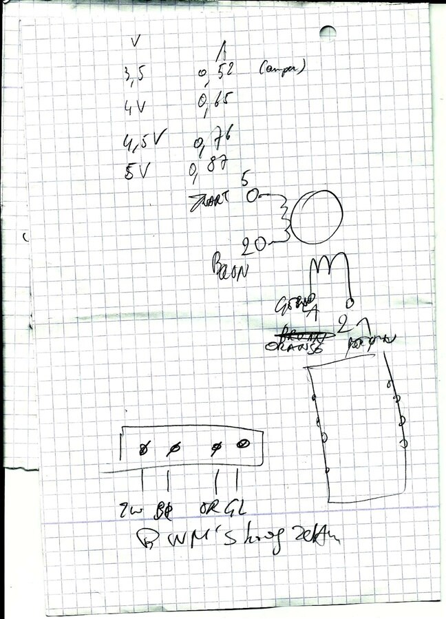
assorted scribbles:
Top Comments