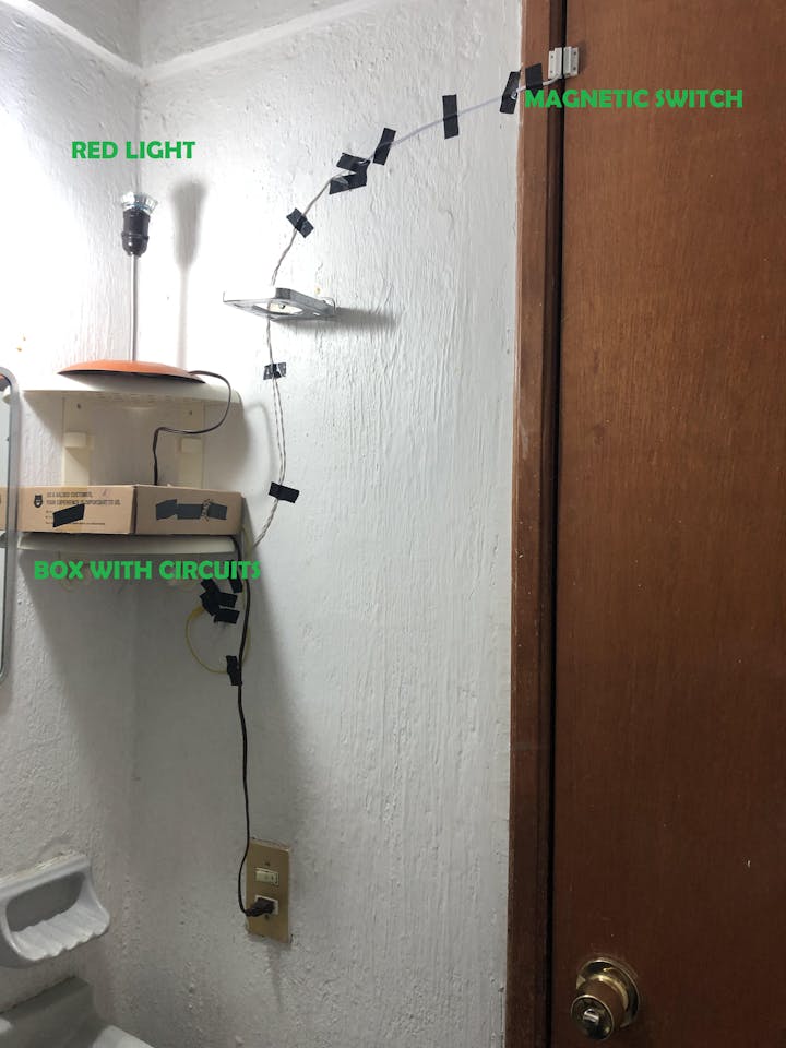
I hosted a Halloween party last Saturday and I placed this simple prank in the bathroom. I used stuff I had at home, I mean at home we have boards, wires, tools, it is more like a small maker space.
I wanted the prank to involve sound and lights but I wasn't sure what would be a good trigger, I thought a PIR sensor would work but I didn't want it to be activated that often, so Abraham had one of those magnetic sensors used for alarms and then I thought the bathroom door would be a good placement for the prank. Whenever the door is opened some seconds after you would hear the psycho theme and some more seconds later another creepy wav file and the lights go ON/OFF.
Things I used:
| Item | Qty |
|---|---|
| 1 | |
| 1 | |
Relay Module | 1 |
Magnetic door sensor | 1 |
Audio Jack 3.5mm cable | 1 |
uUSB cable | 1 |
Speaker with amp | 1 |
Power bank with 2 ports | 1 |
| 1 | |
| Mini breadboard | 1 |
| Crocodile clips | 1 bunch |
| Dupont cables | 1 bunch |
I used Circuit Playground Express to play some wav files. These are the tutorials I followed:
I first used Abraham's speaker with a differential amplifier but I thought it was not loud enough.
I remembered I had a small speaker with rechargeable battery so I decided to use it and a 3.5mm jack with the Circuit Playground Express.
Red cable to A0 pin con CPX and Black cable to GND
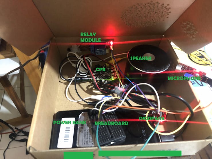
Since I had so little time, I decided to use a Digispark board and a generic audio sensor. A certain amount of noise would switch on/off the light bulb using a relay.
I used crocodile clips and Dupont cables so I didn't have to solder anything. The small breadboard was used to connect power and ground signals.
I put everything in a box and drilled holes for the speaker (a lot). The microphone had to be placed really close to the speaker.
Circuit playground Express and Digispark boards are powered with a 10,000mAh power bank with 2 ports, except for the speaker which had full charge.

Put everything in a box
And the final setup:
Everything placed
The basic wiring:
Diagram draft using fritzing and MS paint
The switch is placed on the door frame and the magnet on the door, so when the door is closed the switch is also closed. In the previous image one of the switch pins is connected to ground, so the Circuit Playground Express will see a 0 on pin A1 when the door is closed.
Magnetic switch placement
When you open the door, the switch will open because it is not near the magnet and since pin A1 is declared with internal pull up, the Circuit Playground Express will see a 1.This is the Circuit Playground Express code:
import time
import board
import digitalio

from adafruit_circuitplayground.express import cpx
switchPin = digitalio.DigitalInOut(board.A1)
switchPin.pull = digitalio.Pull.UP

while True:
  if switchPin.value:
  time.sleep(8)
  #cpx.pixels.fill((255, 0, 0))
  cpx.play_file("psycho.wav")
  #cpx.pixels.fill((0, 0, 0))
  time.sleep(8)
  cpx.play_file("kidsLaugh.wav")
  time.sleep(0.1)
The Arduino code is fair simple whenever a level sound is detected it will toggle the light ON/OFF for a predefined period of time.
int ledPin=1;
int sensorPin=0;
boolean val =0;
unsigned long duration[10] = {400, 900, 500, 300, 200, 150, 800, 600, 100, 250};
int dur = 0;
void setup(){
  pinMode(ledPin, OUTPUT);
  pinMode(sensorPin, INPUT);
}

void loop (){
  val =digitalRead(sensorPin);
  if (val==HIGH) {
    dur = random(0,10);
    digitalWrite(ledPin, LOW);
    delay(duration[dur]);
    digitalWrite(ledPin, HIGH);
    dur = random(0,10);
    delay(duration[dur]);
  }
  else {
    digitalWrite(ledPin, LOW);
  }
}


Top Comments