


Between shipping, working, and the holidays, I haven't had a chance to give my roadtest hardware a good going over... until now!
The Internet of Holiday Lights RoadTest involves three pieces of hardware: The venerable Arduino Uno, its cousin the Arduino Yun, and Infineon's RGB LED Arduino Shield.
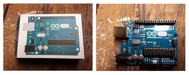
Chances are good that if you've spent any reasonable amount of time making things in the past five years or so, you've heard of Arduinos, and have probably used the Arduino Uno. The Arduino Uno is essentially a breakout board for an ATmega328 8bit microcontroller that gives you access to 14 digital i/o lines and 6 analog input lines. Within those digital i/o lines are two pins which allow you to use I2C devices, and two pins which can be used for serial communications.
The one real caveat of the device is that the ATmega328 doesn't have native USB support, so communications with it is mediated by another chip (the ATmega16U2 in the latest revision of the board) acting as a USB-to-serial converter. What this means is the Uno will only ever appear as a virtual COM port to your computer.
The Arduino Uno is a long time staple of the maker toolkit, and although it lacks the clock speed or large number of i/o lines of some of the larger Arduinos, it's still quite capable and a good starting point for microcontroller based projects.
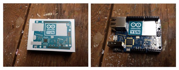
The Yun is a relatively new addition to the Arduino line. It was added just over a year ago, and is an Arduino Leonardo coupled with an Atheros SoC running OpenWRT (for those of you who have never hacked your router - this is a Linux derived firmware designed for embedded networking devices). This means you get the 20 digital i/o lines of a Leonardo (of which, 12 can be used for analog inputs), the native USB support of a Leonardo (which allows the board to appear as a USB HID device or virtual COM port to your computer), and a directly coupled Linux-based network interface that is both wired and wireless.
Just like the Leonardo, the Yun has the same pinout as the Uno, making it compatible with all the same sheilds you may already have bought or developed for the Uno.
Unlike the Leonardo, however, the Yun doesn't have an onboard voltage regulator. This means you can only power it from a 5v source, and exceeding that may damage the board. It also has a microSD slot, which is tied to the Atheros SoC, intended to be used to hold all your settings, served content, and additional packages for use on the web side of your Yun project.
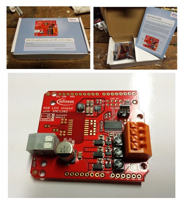
The last hardware component of the roadtest is the truly unique one: Infineon's RGB LED driver sheild for Arduino. This shield, in the configuration supplied, has one power input, one data input, and one power/command data output. It also comes without any headers, so you can easily add simple male headers, or a stackable female header if you intend to use more than one shield with your Arduino.
The level of soldering skill required to assemble the board is minimal, pin headers are just about the easiest soldering project out there, but you will need a soldering iron and some solder to get the board up and running.
The reference manual recommends providing a higher input voltage than what your LEDs' forward voltage requirement is, but it will happily accept anywhere from 12v to 48v as the input. I haven't tested the theory that you may get normal operation by feeding it an input voltage that matches your output voltage, but other members of this roadtest have and seem to have made it work, so your mileage may vary. I'm powering my project off an old HP printer power supply that pushes 36v, so there's more than enough voltage there to run my 12v LED string.
One note: When looking at the silkscreen on the board, you (like me) may misread the labeling for the power input. There is a space above the power input terminals for a DMX chip and input, and the silkscreen on the board has handy labels for that input. If you try to use that label to decide which power input terminal is negative, and which is positive, you're going to wire your power in backward and the shield won't work. Luckily, Infineon was smart enough to realize their users may be quite stupid at times, so reversing the voltage input doesn't seem to damage the board.
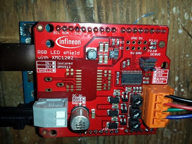
Examining the shield, you can see it fits snugly into an Arduino Uno (or otherwise compatible) pin header for control signal input. Only the I2C pins, and the ground pin, are used so the rest can safely be passed through to additional shields if your setup requires it.
The power input is also quite simple, if you do one better than me and actually manage to read the correct silk screened label. The output is equally simple: There is one pin for the common anode of your LED setup, then one pin each for your red, green, and blue cathodes. It can be used with RGB LED strips or collections of individual LEDs, but it can only drive one color at a time. If you're looking for individually addressable LED control you should look elsewhere.
The input power terminals are of the very simple press to insert friction hold type. They seem quite secure, and should be safe to rely on even without providing some sort of strain relief on the wires themselves. The output power terminals are a little more robust, they're spring tensioned friction hold terminals, and they provide a good strong hold on the wires. I was a little concerned when I first saw these, but none of the wires seem interested in coming loose even after repeated insertions.
The datasheet says the driver can safely deliver 700mA per color, with a peak safe value of 1 A per color line, so you've got a lot of power to work with here. In my early testing it easily lit an entire 5 meter length of LED strip light without complaint, even when asked to drive the entire roll at full white brightness.
There is no Arduino library available for the Infineon board yet, but the development of such a library is an ongoing project associated with this roadtest, so that will likely change soon. Infineon does provide a test program that will walk your lights through a few predetermined colors, and that program is a good resource for understanding how to interact with the board.
I'll go more into how the Infineon board works in later posts, but essentially all the Arduino has to do is perform I2C writes of the parameters you want the LEDs set to. The Infineon board does the rest. The sorts of parameters you set are the brightness fade time, the walking time for going from one color to another, and the intensity of the red, green, and blue LED channels.
So, for example, if you want to make the lights quickly step back and forth between red and green you would set the fade time to zero, the walk time to something very short (say, half a second) in the void setup() phase of your program, then put two items in your main loop(): one setting red to full and everything else to zero, and another setting green to full and everything else to zero.
That's it. No worrying about wait or millis statements to get the transition times right, no bothering with pulse width modulation to get a fade between colors, just set your parameters and you're done. I've only begun putting the board through its paces, but already it seems quite slick.
The Infineon board can also report back the actual current state of the LEDs it is connected to using I2C reads, giving you a fully closed control loop for your lights and opening up quite a few possibilities beyond the simple web-enabled christmas ornaments I'm currently working on.
...next, we'll tackle the software aspect of this roadtest, and begin work on the meat of the project itself. But that's another blog post.
Top Comments