


Interfacing ultra-low power REYAX RYS8830 GNSS Module with Microcontroller.


while working with Tracking devices we need GPS Or GNSS receivers to get the geolocation details. These receivers must be precise by consuming low power, shouldn't have an external antenna, and must be small. Finding the modules with all these specifications really a hectic task. and they won't be available for Proof of concept or production.
In this project, I will provide details to find a low-cost, Ultra low power Consuming, small PCB footprint, Integrated Chip antenna, and secured GNSS included Module based on SONY CXD5605AGF Engine.

REYAX is One of the leading total solutions providers of wireless modules. REYAX has huge wireless products, you can go follow their website for more information REYAX GPS/GNSS product RYS8830 is one of the good options for portable, low-power-consuming tracking applications.
In this Project, I will showcase a demo of how to interface RYS8830 With the microcontroller and how to use the module to collect the GeoLocation Details.
To start the project we must know the features and specifications of the module let's go through those Details First.
Features
- RYS8830 is built on the high performance of the SONY CXD5605AGF GNSS engine.
- multi-GNSS receiver for GPS, GLONASS, SBAS, QZSS, BeiDou, and Galileo.
- Small SMD form factor 11mm*11mm*2.2mm(Half the Size Of the CR2032 Battery).
- Ultra-low power consumption with Embedded Chip antenna.
- I2C/UART modes are available to communicate with the Host Microcontroller.
- Only a Few commands are required to communicate with the host microcontroller.
- Users can select the satellite system to be used for positioning
Specifications
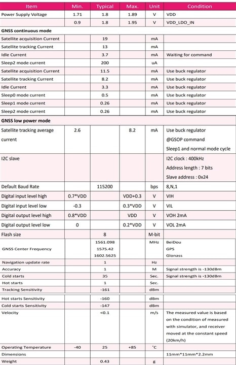
Note: Now You got to know that the RYS8830 Operating Voltage Level is 1.8 Volt, Which means The Logic voltage of the module is 1.8V.
To Communicate with the RYS8830, the host microcontroller Also Need to be at the same Logic Voltage Level as RYS8830. RYS8830 can't be directly interfaced with a higher voltage level host microcontroller. if you interface RYS8830 With 5 volt or 3.3-volt logic voltage microcontroller you will ruin the module. To avoid this use a logic voltage shifter to interface the RYS8830 with High logic voltage microcontroller. In this project have used N-Channel Enhancement Mode FET(2N7002) to create a logic Level shifter.

To Collect the Geolocation Details From RYS8830 we can choose between I2C/UART Modes. In This Project, I am using UART Mode to communicate RYS8830 and NodeMCU. The RYS8830 has the 115200 Fixed Baud Rate to communicate in UART Mode.
RYS8830 Search mode select
All the standard GPS/GNSS Modules will have Three types of search modes Namely Hot start, Cold Start, and Warm Start. based on the Search mode GNSS monitor will start to fix the position.
Commands For Search mode selection
- Hot start: @GSR
- Warm start: @GSW
- Cold start: @GCD
In this project, I will explain only the Utilized Commands to Communicate between RYS8830 And NodeMCU using UART.
1.) @GSTP // Positioning stop
This command is used to stop the positioning. The RYS8830/RYS8833 transfers to the Idle state.
2.) @GNS 47 // Positioning-use satellite use GPS + GLONASS + SBAS + QZSS L1-CA + QZSS L1-S
This command is used to select the satellite systems to be used for positioning. The satellite systems are assigned to the bits of the argument. “1” is set for the bits of the systems which are to be used and “0” is set for the bits of the systems which are not to be used. Arguments can be specified in decimal or hexadecimal notation. With hexadecimal notation, add “0x” in front of the numeral. Only 2 satellite systems can be selected from GLONASS, BeiDou, and Galileo. If over 2 satellite systems are selected from these satellite systems, an error will return (-EINVAL). Furthermore, GLONASS and BeiDou cannot be selected at the same time.
3.) @GPPS 1 // enable 1PPS function
This command is used to control 1PPS output. When 1PPS output is enabled, the timing pulse is output in a 1 sec period from the 1PPS output port after clock information is received from GNSS. When 1PPS output is disabled, the timing pulse is not output from the 1PPS output port.
4.) @GSR // hot start
This command is used to start positioning using a hot start. The TTFF is prioritized until the first fix. TTFF is about 1s shorter than @GSP but the position accuracy is somewhat worse than @GSP. There is no difference with @GSP after the first fix. When the conditions for the hot start have not been met, positioning is started automatically using a warm start or cold start.
*For a detailed command user guide, please refer to RYS8830_RYS8833_Software_Guide
In this project, I am using NodeMCU as the main microcontroller and OLED to display the Geolocation details. It is required to key in “enter” or “\r\n” at the end of all Commands to communicate with the RYS8830. After receiving the command RYS8830 Response back With an acknowledgment. for this demo, I am disabling the 1PPS function. I have utilized the Tiny GPS++ Library to collect the geolocation details in an Easy form
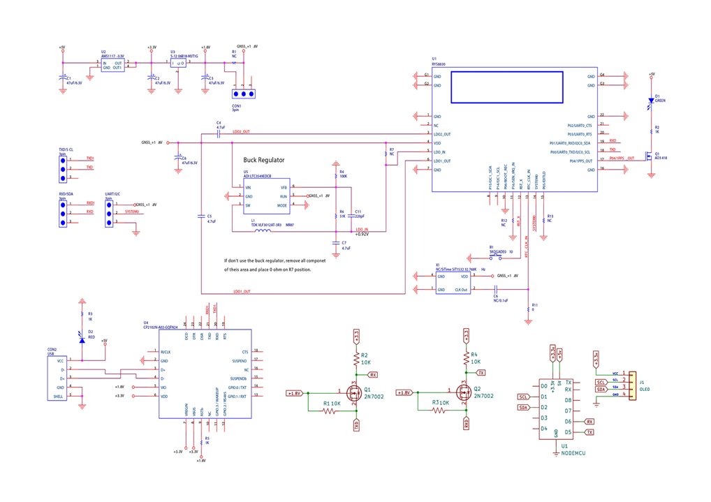
You can find the code and schematic to interface RYS8830 With the Microcontroller.
In the Demo video, you can find how the geolocation Details are received and displayed on the OLED
Demo Video
Code
#include <TinyGPS++.h>
#include <SoftwareSerial.h>
static const int RXPin = D5, TXPin = D6;
static const uint32_t GPSBaud = 115200;
#include <Wire.h>
#include <Adafruit_GFX.h>
#include <Adafruit_SSD1306.h>
// The TinyGPS++ object
TinyGPSPlus gps;

// The serial connection to the GPS device
SoftwareSerial ss(RXPin, TXPin);
#define SCREEN_WIDTH 128 // OLED display width, in pixels
#define SCREEN_HEIGHT 64 // OLED display height, in pixels
Adafruit_SSD1306 display(SCREEN_WIDTH, SCREEN_HEIGHT, &Wire, -1);
void setup()
{
  Serial.begin(115200);
  ss.begin(GPSBaud);
ss.print("@GSTP\r\n");//positioning stop
  delay(500);
  ss.print("@GNS 47\r\n");// Positioning-use satellite use GPS + GLONASS + SBAS + QZSS L1-CA + QZSS L1-S
  delay(500);
 // ss.print("@GPPS 1\r\n");// enable 1PPS function
 // delay(500);
  ss.print("@GSR\r\n");// hot start
  delay(2000);

  if(!display.begin(SSD1306_SWITCHCAPVCC, 0x3C)) { // Address 0x3D for 128x64
    Serial.println(F("SSD1306 allocation failed"));
    for(;;);
  }
  delay(2000);
  display.clearDisplay();

}

void loop()
{
  // This sketch displays information every time a new sentence is correctly encoded.
  while (ss.available() > 0)
    if (gps.encode(ss.read()))
      displayInfo();

  if (millis() > 5000 && gps.charsProcessed() < 10)
  {
    Serial.println(F("No GPS detected: check wiring."));
    while(true);
  }
}

void displayInfo()
{
  Serial.print(F("Location: "));
  if (gps.location.isValid())
  {
    Serial.print(gps.location.lat(), 6);
    Serial.print(F(","));
    Serial.print(gps.location.lng(), 6);
  }
  else
  {
    Serial.print(F("INVALID"));
  }

  Serial.print(F("  Date/Time: "));
  if (gps.date.isValid())
  {
    Serial.print(gps.date.month());
    Serial.print(F("/"));
    Serial.print(gps.date.day());
    Serial.print(F("/"));
    Serial.print(gps.date.year());
  }
  else
  {
    Serial.print(F("INVALID"));
  }

  Serial.print(F(" "));
  if (gps.time.isValid())
  {
    if (gps.time.hour() < 10) Serial.print(F("0"));
    Serial.print(gps.time.hour());
    Serial.print(F(":"));
    if (gps.time.minute() < 10) Serial.print(F("0"));
    Serial.print(gps.time.minute());
    Serial.print(F(":"));
    if (gps.time.second() < 10) Serial.print(F("0"));
    Serial.print(gps.time.second());
    Serial.print(F("."));
    if (gps.time.centisecond() < 10) Serial.print(F("0"));
    Serial.print(gps.time.centisecond());
  }
  else
  {
    Serial.print(F("INVALID"));
  }

  Serial.println();
  display.setTextSize(1);
  display.setTextColor(WHITE);


  display.setCursor(0,10);
  display.print("Latitude:");
  display.print(gps.location.lat(), 6);
  display.setCursor(0,30);
  display.print("Longitude:");
  display.print(gps.location.lng(), 6);

  display.display();
  delay(1000);
  display.clearDisplay();
}


