element14 Community
element14 Community
    Register Log In
  • Site
  • Search
  • Log In Register
  • Community Hub
    Community Hub
    • What's New on element14
    • Feedback and Support
    • Benefits of Membership
    • Personal Blogs
    • Members Area
    • Achievement Levels
  • Learn
    Learn
    • Ask an Expert
    • eBooks
    • element14 presents
    • Learning Center
    • Tech Spotlight
    • STEM Academy
    • Webinars, Training and Events
    • Learning Groups
  • Technologies
    Technologies
    • 3D Printing
    • FPGA
    • Industrial Automation
    • Internet of Things
    • Power & Energy
    • Sensors
    • Technology Groups
  • Challenges & Projects
    Challenges & Projects
    • Design Challenges
    • element14 presents Projects
    • Project14
    • Arduino Projects
    • Raspberry Pi Projects
    • Project Groups
  • Products
    Products
    • Arduino
    • Avnet Boards Community
    • Dev Tools
    • Manufacturers
    • Multicomp Pro
    • Product Groups
    • Raspberry Pi
    • RoadTests & Reviews
  • Store
    Store
    • Visit Your Store
    • Choose another store...
      • Europe
      •  Austria (German)
      •  Belgium (Dutch, French)
      •  Bulgaria (Bulgarian)
      •  Czech Republic (Czech)
      •  Denmark (Danish)
      •  Estonia (Estonian)
      •  Finland (Finnish)
      •  France (French)
      •  Germany (German)
      •  Hungary (Hungarian)
      •  Ireland
      •  Israel
      •  Italy (Italian)
      •  Latvia (Latvian)
      •  
      •  Lithuania (Lithuanian)
      •  Netherlands (Dutch)
      •  Norway (Norwegian)
      •  Poland (Polish)
      •  Portugal (Portuguese)
      •  Romania (Romanian)
      •  Russia (Russian)
      •  Slovakia (Slovak)
      •  Slovenia (Slovenian)
      •  Spain (Spanish)
      •  Sweden (Swedish)
      •  Switzerland(German, French)
      •  Turkey (Turkish)
      •  United Kingdom
      • Asia Pacific
      •  Australia
      •  China
      •  Hong Kong
      •  India
      •  Korea (Korean)
      •  Malaysia
      •  New Zealand
      •  Philippines
      •  Singapore
      •  Taiwan
      •  Thailand (Thai)
      • Americas
      •  Brazil (Portuguese)
      •  Canada
      •  Mexico (Spanish)
      •  United States
      Can't find the country/region you're looking for? Visit our export site or find a local distributor.
  • Translate
  • Profile
  • Settings
Arduino
  • Products
  • More
Arduino
Blog UNO, Blue Man and the Neon Light
  • Blog
  • Forum
  • Documents
  • Quiz
  • Events
  • Polls
  • Files
  • Members
  • Mentions
  • Sub-Groups
  • Tags
  • More
  • Cancel
  • New
Join Arduino to participate - click to join for free!
  • Share
  • More
  • Cancel
Group Actions
  • Group RSS
  • More
  • Cancel
Engagement
  • Author Author: jc2048
  • Date Created: 8 Dec 2019 1:26 PM Date Created
  • Views 4277 views
  • Likes 15 likes
  • Comments 9 comments
  • boost
  • ardexpert
  • ard_expert
  • neon
  • uno
  • jc2048
  • arduino uno project
  • arduino
  • inductor
Related
Recommended

UNO, Blue Man and the Neon Light

jc2048
jc2048
8 Dec 2019


WARNING: This blog involves high voltages around sensitive low-voltage devices. Take great care if you decide to try this for yourself.


Recently, I received a swag pack that included an UNO and a Blue Man so I thought I'd do a very short and simple experimenting-type blog that could, maybe, lead on to something seasonal.


Here they are, the BM and UNO, along with some of the components I'm going to use: a 2k7 resistor; an MPS42A transistor; a 10mH inductor; and a neon bulb.


image


I'd previously found a bag of neon bulbs that I must have bought for something or other and then never used.


image


To get the neon to light up, I'm going to need to generate a fairly high voltage. Although I was going to try it with just the components shown above, I then chickened out and added a bit more protection. I didn't know how long it would take the neon to strike, so there was the possibility the voltage might damage the transistor and, once that was gone, might even go on to cause damage to the input of the 'scope. I didn't care about a single, dead transistor, but I do care about my oscilloscope. So I thought of adding a zener to clamp the voltage but didn't have anything suitable so I fell back to using a MOSFET (IRF510) as a zener.


Here's the circuit I ended up with.


image


[Transistor type should be MPS42A.]


The circuit is a very crude boost converter. The UNO turns the transistor on for about 60us and that allows the coil current to steadily ramp up. When the transistor turns off, the coil generates an emf to keep the current flowing so that it can 'discharge' the energy that is stored in its magnetic field.


Of course, it then dawned on me that I might as well have used the MOSFET as the switch and not bothered with the BJT at all but I left it as it was.


Here are a couple of shots of it 'bird's nested' above the UNO.


image


image


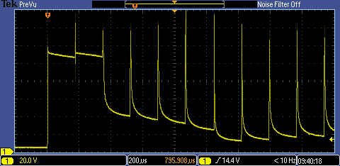
Here is the waveform as it starts off


image


The spikes are the points where the transistor turns off and the voltage leaps up. The first two times the neon doesn't strike and the voltage is being clamped by the zener [MOSFET]. On the third cycle, the neon strikes and, from then on, the warm, ionized gas strikes every time. I put the small capacitor in the circuit to give the neon a helping hand at the start. It isn't enough to power it through a cycle but it keeps the voltage up at the start and allows the gas to ionize - without it, the neon doesn't ever get started.


This is more detail of one of the later cycles


image


Here's what it looks like when it's running


You don't have permission to edit metadata of this video.
Edit media
x
image
Upload Preview
image


Although it's non too clear from the video, because I'm driving it with dc the glow is only around the negative electrode (the lefthand one in the picture below):


image


If it's of any interest, this is the code I was using:


int outPin = 9;   // output pin to use  
// the setup routine runs once when you press reset:
void setup() {
  // set output pin:
  pinMode(outPin, OUTPUT);
}
// the loop routine runs over and over again forever:
void loop() {
word onPeriod = 0;
  // neon on 
  for(onPeriod=0;onPeriod<6000;onPeriod++) {    // repeat for about a second
    noInterrupts();
    digitalWrite(outPin, HIGH);   // pin is high
    delayMicroseconds(100);        // for 100 microseconds
    digitalWrite(outPin, LOW);    // then low
    interrupts();
    delayMicroseconds(60);        // for 60 microseconds
    }
  // neon off
  delay(1000);   // off for a second
}


That was good fun. A nice flickering effect. Must be able to use that for something.


Update 18th December


Here's something a bit more seasonal. I've used five neons in the shape of a star (each neon has a 100k in series: there was a tendency for one or two to strike and hold off the rest otherwise). Quite by accident, I've contrived a situation where it's all a bit 'touch and go' and the behaviour of the resulting plasma in the bulb is fairly chaotic, giving the nice flickering effect.


You don't have permission to edit metadata of this video.
Edit media
x
image
Upload Preview
image


Glad I don't have to try and get this through an EMC conformance test.


Update 27th December


Finally, the Blue Man waving a glowing 'torch'. It was falling apart as I was videoing it, but it will do for now.


You don't have permission to edit metadata of this video.
Edit media
x
image
Upload Preview
image


If you found this interesting and would like to see more blogs I've written, a list can be found here: jc2048 Blog Index

  • Sign in to reply

Top Comments

  • Jan Cumps
    Jan Cumps over 5 years ago +5
    Next time I get a blue man, I'm going to drill 2 holes in its back of the head and put LEDs inside. Then blink them. A nice flickering effect. Must be able to use that for something. XMAS time is coming…
  • jc2048
    jc2048 over 5 years ago +5
    Here is how the current through the neon looks. I've added an additional 12V zener to the MOSFET to lift the voltage it clamps to to about 125V. A 100R resistor on the ground side of the neon bulb lets…
  • jc2048
    jc2048 over 5 years ago in reply to ciaburrj +3
    Here it is driven by PWM. Pin 9 [pb1] also happens to be OC1A, so I set up timer 1 to do fast PWM on that output. The clock is with a divide by 8 prescaler, so the unit interval is 16MHz/8 = 2MHz (0.5us…
  • jc2048
    jc2048 over 5 years ago in reply to Jan Cumps

    image

    • Cancel
    • Vote Up +3 Vote Down
    • Sign in to reply
    • More
    • Cancel
  • Jan Cumps
    Jan Cumps over 5 years ago

    Where did you get the inspiration to use the FET as a Zener diode?

    • Cancel
    • Vote Up +3 Vote Down
    • Sign in to reply
    • More
    • Cancel
  • jc2048
    jc2048 over 5 years ago in reply to ciaburrj

    Here it is driven by PWM.


    image


    Pin 9 [pb1] also happens to be OC1A, so I set up timer 1 to do fast PWM on that

    output. The clock is with a divide by 8 prescaler, so the unit interval is 16MHz/8

    = 2MHz (0.5us).


    That works nicely.


    Here's the code. This is very specific to the UNO because I'm going straight for

    the registers.


    /* neon boost pwm version */
    /* specific to UNO */
    
    void setup() {
      // timer 1 pwm setup
      DDRB = DDRB | 0x02;    // set pin 9 as output
      OCR1A = 0x78;         //high time = 120 (x0.5us = 60 us) 
      ICR1 = 0xC8;          //period = 200 (x0.5us = 100us)
      TCCR1A = 0x82;        //set at start, end at match
      TCCR1B = 0x1A;        //fast pwm, mode 13,clk/8=0.5us
    }
    
    void loop() {
    }


    If anyone wants to use this, bear in mind that libraries will sometimes take over

    timer 1 for their own use, so there is lots of potential for conflict with other

    code.

    • Cancel
    • Vote Up +3 Vote Down
    • Sign in to reply
    • More
    • Cancel
  • jw0752
    jw0752 over 5 years ago

    Hi Jon,


    I love your air wiring constructions. It reminds me of how I used to make my kids practice soldering techniques by having them construct cubes and pyramids out of wire clippings. Another interesting project build!


    John

    • Cancel
    • Vote Up +2 Vote Down
    • Sign in to reply
    • More
    • Cancel
  • jc2048
    jc2048 over 5 years ago in reply to ciaburrj

    Good idea. You could use PWM, but you'd have to be careful how you set it up.


    This trace shows the coil current (yellow) and the pin 9 output (blue):


    image


    When pin 9 is high, the transistor is on, the coil has 5V across it and the coil

    current ramps up from zero. With a 10mH coil, it gets to 50mA after about 100us.


    You don't want the ramping up period to go on too long or you'll get to the limit

    of what the transistor can manage (a few hundred milliamps).


    The time driving the neon is then quite short, about 10us, so I could have had a

    shorter off time (my 60us was a bit of an arbitrary choice).


    The standard PWM period on the UNO is something like 500Hz, unless you reprogram

    the registers directly, so it would give a much longer off period. But if you sped

    it up, it would be the ideal way to do this as it would give precise timing in the

    background.


    Reviewing what I've done here, it looks like I might have done better with a 1mH or

    2.2mH coil over about 10-20us (which is still quite manageable for a micro doing

    the timing).


    It's also noticeable that quite a lot of the energy is going to the zener clamp and

    not the neon (the neon current is only getting to 20mA, or so, whereas the coil is

    pushing out about 50mA initially). So not a particularly efficient circuit.


    I like your Blue Man idea. I'll try that later when I have some time.

    • Cancel
    • Vote Up +2 Vote Down
    • Sign in to reply
    • More
    • Cancel
>
element14 Community

element14 is the first online community specifically for engineers. Connect with your peers and get expert answers to your questions.

  • Members
  • Learn
  • Technologies
  • Challenges & Projects
  • Products
  • Store
  • About Us
  • Feedback & Support
  • FAQs
  • Terms of Use
  • Privacy Policy
  • Legal and Copyright Notices
  • Sitemap
  • Cookies

An Avnet Company © 2025 Premier Farnell Limited. All Rights Reserved.

Premier Farnell Ltd, registered in England and Wales (no 00876412), registered office: Farnell House, Forge Lane, Leeds LS12 2NE.

ICP 备案号 10220084.

Follow element14

  • X
  • Facebook
  • linkedin
  • YouTube