element14 Community
element14 Community
    Register Log In
  • Site
  • Search
  • Log In Register
  • Community Hub
    Community Hub
    • What's New on element14
    • Feedback and Support
    • Benefits of Membership
    • Personal Blogs
    • Members Area
    • Achievement Levels
  • Learn
    Learn
    • Ask an Expert
    • eBooks
    • element14 presents
    • Learning Center
    • Tech Spotlight
    • STEM Academy
    • Webinars, Training and Events
    • Learning Groups
  • Technologies
    Technologies
    • 3D Printing
    • FPGA
    • Industrial Automation
    • Internet of Things
    • Power & Energy
    • Sensors
    • Technology Groups
  • Challenges & Projects
    Challenges & Projects
    • Design Challenges
    • element14 presents Projects
    • Project14
    • Arduino Projects
    • Raspberry Pi Projects
    • Project Groups
  • Products & Partners
    Products & Partners
    • Arduino
    • Avnet & Tria Boards Community
    • Dev Tools
    • Manufacturers
    • Multicomp Pro
    • Product Groups
    • Raspberry Pi
    • RoadTests & Reviews
  • About Us
    About the element14 Community
  • Store
    Store
    • Visit Your Store
    • Choose another store...
      • Europe
      •  Austria (German)
      •  Belgium (Dutch, French)
      •  Bulgaria (Bulgarian)
      •  Czech Republic (Czech)
      •  Denmark (Danish)
      •  Estonia (Estonian)
      •  Finland (Finnish)
      •  France (French)
      •  Germany (German)
      •  Hungary (Hungarian)
      •  Ireland
      •  Israel
      •  Italy (Italian)
      •  Latvia (Latvian)
      •  
      •  Lithuania (Lithuanian)
      •  Netherlands (Dutch)
      •  Norway (Norwegian)
      •  Poland (Polish)
      •  Portugal (Portuguese)
      •  Romania (Romanian)
      •  Russia (Russian)
      •  Slovakia (Slovak)
      •  Slovenia (Slovenian)
      •  Spain (Spanish)
      •  Sweden (Swedish)
      •  Switzerland(German, French)
      •  Turkey (Turkish)
      •  United Kingdom
      • Asia Pacific
      •  Australia
      •  China
      •  Hong Kong
      •  India
      •  Japan
      •  Korea (Korean)
      •  Malaysia
      •  New Zealand
      •  Philippines
      •  Singapore
      •  Taiwan
      •  Thailand (Thai)
      •  Vietnam
      • Americas
      •  Brazil (Portuguese)
      •  Canada
      •  Mexico (Spanish)
      •  United States
      Can't find the country/region you're looking for? Visit our export site or find a local distributor.
  • Translate
  • Profile
  • Settings
Arduino
  • Products & Partners
  • More
Arduino
Arduino Forum Have a question about Arduino? Ask me!
  • Blog
  • Forum
  • Documents
  • Quiz
  • Events
  • Polls
  • Files
  • Members
  • Mentions
  • Sub-Groups
  • Tags
  • More
  • Cancel
  • New
Join Arduino to participate - click to join for free!
Actions
  • Share
  • More
  • Cancel
Forum Thread Details
  • Replies 1914 replies
  • Subscribers 527 subscribers
  • Views 69777 views
  • Users 0 members are here
  • jeremy_blum
  • expert
  • student
  • arduino
Related

Have a question about Arduino? Ask me!

sciguy14
sciguy14 over 15 years ago

This thread has been closed to new questions.

However, we welcome you to Post Your Questionabout Arduino in the element14 Community Arduino group.  You'll find many fellow members and experts who have just the answer you're looking to find! 


Thank You, Your Friends at element14 Community


image

Jeremy Blum

Jeremy is an Electrical and Computer Engineering Student at Cornell University. He has been building microcontroller projects since high school, from a prototype prosthetic hand with a novel control scheme, to a nerf gun that fires at the intruders and uploads their picture to the web.
  • Sign in to reply
  • Cancel

Top Replies

  • billabott
    billabott over 13 years ago in reply to e14 Contributor +2
    @Brendan Your video is somewhat adequate for the intended purpose, however, from an engineer's point of view it is lacking in providing pertinent facts. Such as the part number, data sheet, and source…
  • e14 Contributor
    e14 Contributor over 15 years ago +1
    Jeremy, thanks for your intro videos. I am just getting started myself in Arduino though I have done some simple electronics projects using Atmel chips. Here is an example using ATTiny13 chips. www.youtube…
  • e14 Contributor
    e14 Contributor over 15 years ago +1
    Hi Jeremy I've built a device (see picture) with an Arduino and Ethernet shield that connects to our Network Monitor (Nagios) and moves an arrow to indicate if any of the computers we monitor are not responding…
  • e14 Contributor
    e14 Contributor over 15 years ago

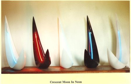
    Jeremy Blum, I need an electrical engineer knowledgeable in DC Volt milliamp. I need circuitry developed to facilitate remote signaling for lite sculpture using neon/argon plasma effects- can you help or direct me? Ray Kimage

    • Cancel
    • Vote Up 0 Vote Down
    • Sign in to reply
    • Cancel
  • sciguy14
    sciguy14 over 15 years ago in reply to driggs

    No, you need a sim card carrier.  I don't know of any devices like that that work on CDMA.

    • Cancel
    • Vote Up 0 Vote Down
    • Sign in to reply
    • Cancel
  • sciguy14
    sciguy14 over 15 years ago in reply to e14 Contributor

    I don't really know what you want...  Can you be more specific?

    • Cancel
    • Vote Up 0 Vote Down
    • Sign in to reply
    • Cancel
  • e14 Contributor
    e14 Contributor over 15 years ago in reply to sciguy14

    What is a CDMA?

    • Cancel
    • Vote Up 0 Vote Down
    • Sign in to reply
    • Cancel
  • billabott
    billabott over 15 years ago in reply to e14 Contributor

    follow this link for a explanation of CDMA    http://lmgtfy.com/?q=cdma

    • Cancel
    • Vote Up 0 Vote Down
    • Sign in to reply
    • Cancel
  • e14 Contributor
    e14 Contributor over 15 years ago

    Hi Jeremy, thanks for the great tutorials.


    In the tutorial 04 analog inputs, I tried to use a microphone instead of a photo resistor to dim LED, but it doesn't work.


    Could you give me an advice?


    Thank you once again


    --

    Hong

    • Cancel
    • Vote Up 0 Vote Down
    • Sign in to reply
    • Cancel
  • e14 Contributor
    e14 Contributor over 15 years ago in reply to sciguy14

    sorry u could not go the diastance Jearemy

    • Cancel
    • Vote Up 0 Vote Down
    • Sign in to reply
    • Cancel
  • e14 Contributor
    e14 Contributor over 15 years ago

    Jeremy:  I'm a volunteer firefighter in my county, and I am looking to design a system that I think the Ardunio will work with.  I'm hoping you can either help me with this a little, or if I'm barking up the wrong tree, steer me in the right direction.


    Here's what I've got going:


    Currently, I have a two strobe system installed on my personal truck, which I use for responding to emergency calls.


    The first system is simply two independant rectangular LED heads (which can be synced to each other) with built in controllers that has about 15 different flash patterns programmed in.  This system can not be modified, and I'm not looking to do that anyway - just please read on and hopefully I can explain what I'm trying to do.


    The second system is what is called a Six Head Strobe Pack/Kit.  It consists of six strobe lights, mounted in the headlights, front turn signals, and rear brake lights.  This system has a master control module with 24 different patterns, plus the ability to enable or disable the strobes is various configurations.


    At the moment, I am using simple analog switches to turn on/off both systems, a switch to sync the LED heads, a two way momentary switch to change their patterns either indiviually or together if they are in Sync mode, a switch to change the Strobe pack between High/Low power, a switch to enable heads 1-4, a switch to enable heads 5-6, and a switch to change the strobe pattern.


    What bugs me about this system (which I did build myself) is that it has no way to tell me what pattern I'm using with either system, and I have to know which pattern I'm on, and then push the correct button for each system x-# of times to get to the pattern I want.


    Additionally, when I am using the system, if for some reason I choose to shut down my truck (due to length of the call in order to save gas), I have to stay on top of my strobe systems or they'll suck the battery dry and then of course, I have to ask for a jump from my fellow firefighters.


    Now, that just touches on the basics of what I want to do...  And I apologize for this being such a long reply, but I feel it's better if you fully understand what I want to do:


    I want to digitally control both strobe systems, using a chip of some sort.  The following requirements need to be met:

    1) Has to display (on some sort of digital LCD) the current pattern for the selected Strobe system

    2) Has to allow me to switch patterns either with a single push of the button for each pattern, OR, allow me to enter/select the pattern I want from the ones in memory, and then programatically, simulate a button push for the appropriate controller x-# of times until the correct pattern is reached.

    3) Has to know (memory) which pattern is currently selected, and NOT FORGET the current selected pattern, even if the vehicle battery is dead (3.3V button cell battery to keep the memory charged?)

    4) Has to allow me to change the various options for each strobe system and store them in memory

    5) The display should be dimmable through the vehicles Dimmer control knob

    6) The system MUST monitor vehicle voltage, and if it drops below x-volts, must shut down the strobes.

    7) The system SHOULD enter a "power saving" mode when it detects that I have turned off the vehicle - so that the strobes run for say, 15 seconds, then shut down for 30, then run again for 15 more...  The times should be user seletable.

    8) the LCD backlight should switch from + to - display mode or vice versa depending on time of day (day/night mode operation).

    9) the LCD will switch between showing the current flash pattern for each strobe system, the current time, the current voltage of the vehicle, and so on.

    10) I may, in the future, decide to add additional features, such as current GPS location (why I'd do this I don't know yet, but I've thought about it a little)

    11) Last, it should be expandable for up to four strobe systems.


    This is just the basics of what I'm looking for.  I plan to build this myself.  I have extensive electrical (not electronics) and computer systems/networking experience, but only limited electronics experience.  I know how to solder, cut wires, and make my own electrical circuits, but my experience with electronics is limited.


    Here are my quesitons:


    1) is the Ardunio the chip I want to use?

         a) If so, which flavor?

         b) If not, what should I use?

    2) I think I know what sort of LCD I need, and where to get it, but if you have suggestions, I'm all ears.

    3) Once I complete the concept, I want a printed circuit board for the system.  I'll use a breadboard for testing.  Where should I go to get one made?

    4) I'd like to use a series of mini-switches - some that will control the module's functions, and others that will allow me to select menu items, and a couple for quick short cuts (such as one that will change the current selected strobe system, and one that will change the flash pattern of the current selected system).

    5) I've thought about possibly using a touch screen, but I am currently not in favor of that, as it takes one of the driver's hands off the wheel and eyes off the road in order to touch the screen.  A button push is IMHO faster.... you only have to take your eyes off the road for a second, locate the button, and push it... with a touch screen, you have to verify that it "read" the push...  what are your thoughts on this?


    Again, I realize this is quite a list.  If you or anyone else out there is interested in assisting me with this project, please let me know, and/or share any insight you have here.


    I don't see a way to attach any files that might help you understand this project better, but I can send them to you if you feel they might help.  The first is a wiring diagram of the currently wired system (Power Point and/or Visio), and the second is a detailed breakdown of what I want the new controller head to do (Word).


    Thanks!


    V/R


    Black-Wolf

    • Cancel
    • Vote Up 0 Vote Down
    • Sign in to reply
    • Cancel
  • sciguy14
    sciguy14 over 15 years ago in reply to e14 Contributor

    A microphone is a diaphragm that vibrates back and forth and generates a voltage waveform with a frequency corresponding to the pitch of the sound it received, and an amplitude proportional to the volume.  So, you can't just treat it like an analog input.  You'll need to use a frequency to voltage converter if you want to vary voltage based on frequency.  If you want to vary voltage based on volume, put it in series with a diode to kill the negative hald of the waveform, and use a capacitor to smooth the input value.  This will basically make a half-wave rectifier, which when sampled will give you an RMS voltage approximately equivlant to the volume.  It's not a perfect Solution, but it should get the job done.


    Half Wave Recitifiers: http://en.wikipedia.org/wiki/Rectifier#Half-wave_rectification

    RMS Voltage: http://en.wikipedia.org/wiki/Root_mean_square

    • Cancel
    • Vote Up 0 Vote Down
    • Sign in to reply
    • Cancel
  • sciguy14
    sciguy14 over 15 years ago in reply to e14 Contributor

    Marc,


    That's a pretty ambitious project, but it sounds really cool! 


    1. It's certainly feasible, and I think the Arduino Mega 2560 would be a good choice for this project.

    2. Do you want an LCD character display or something with greater resolution?  For the former, something like this would be good: http://www.sparkfun.com/products/256.  For the latter, I suggest this: http://www.sparkfun.com/products/710.  You could go for a color screen, but I think it would be more trouble than it's worth.

    3. Since this is small production scale, you'll be best off with a batch PCB service like this: http://batchpcb.com/index.php/Products, or this: http://dorkbotpdx.org/wiki/pcb_order

    4. That sounds like a great idea.  Just configure them as digital inputs into one of the pins on the arduino mega.

    5. I agrre that you shouldn't use a touch screen.  It will be a huge pain to get work, and will likely be distracting.


    Let me know if you have other questions, this sounds like a great idea!

    • Cancel
    • Vote Up 0 Vote Down
    • Sign in to reply
    • Cancel
<>
element14 Community

element14 is the first online community specifically for engineers. Connect with your peers and get expert answers to your questions.

  • Members
  • Learn
  • Technologies
  • Challenges & Projects
  • Products
  • Store
  • About Us
  • Feedback & Support
  • FAQs
  • Terms of Use
  • Privacy Policy
  • Legal and Copyright Notices
  • Sitemap
  • Cookies

An Avnet Company © 2026 Premier Farnell Limited. All Rights Reserved.

Premier Farnell Ltd, registered in England and Wales (no 00876412), registered office: Farnell House, Forge Lane, Leeds LS12 2NE.

Follow element14

  • X
  • Facebook
  • linkedin
  • YouTube