element14 Community
element14 Community
    Register Log In
  • Site
  • Search
  • Log In Register
  • About Us
  • Community Hub
    Community Hub
    • What's New on element14
    • Feedback and Support
    • Benefits of Membership
    • Personal Blogs
    • Members Area
    • Achievement Levels
  • Learn
    Learn
    • Ask an Expert
    • eBooks
    • element14 presents
    • Learning Center
    • Tech Spotlight
    • STEM Academy
    • Webinars, Training and Events
    • Learning Groups
  • Technologies
    Technologies
    • 3D Printing
    • FPGA
    • Industrial Automation
    • Internet of Things
    • Power & Energy
    • Sensors
    • Technology Groups
  • Challenges & Projects
    Challenges & Projects
    • Design Challenges
    • element14 presents Projects
    • Project14
    • Arduino Projects
    • Raspberry Pi Projects
    • Project Groups
  • Products
    Products
    • Arduino
    • Avnet Boards Community
    • Dev Tools
    • Manufacturers
    • Multicomp Pro
    • Product Groups
    • Raspberry Pi
    • RoadTests & Reviews
  • Store
    Store
    • Visit Your Store
    • Choose another store...
      • Europe
      •  Austria (German)
      •  Belgium (Dutch, French)
      •  Bulgaria (Bulgarian)
      •  Czech Republic (Czech)
      •  Denmark (Danish)
      •  Estonia (Estonian)
      •  Finland (Finnish)
      •  France (French)
      •  Germany (German)
      •  Hungary (Hungarian)
      •  Ireland
      •  Israel
      •  Italy (Italian)
      •  Latvia (Latvian)
      •  
      •  Lithuania (Lithuanian)
      •  Netherlands (Dutch)
      •  Norway (Norwegian)
      •  Poland (Polish)
      •  Portugal (Portuguese)
      •  Romania (Romanian)
      •  Russia (Russian)
      •  Slovakia (Slovak)
      •  Slovenia (Slovenian)
      •  Spain (Spanish)
      •  Sweden (Swedish)
      •  Switzerland(German, French)
      •  Turkey (Turkish)
      •  United Kingdom
      • Asia Pacific
      •  Australia
      •  China
      •  Hong Kong
      •  India
      •  Korea (Korean)
      •  Malaysia
      •  New Zealand
      •  Philippines
      •  Singapore
      •  Taiwan
      •  Thailand (Thai)
      • Americas
      •  Brazil (Portuguese)
      •  Canada
      •  Mexico (Spanish)
      •  United States
      Can't find the country/region you're looking for? Visit our export site or find a local distributor.
  • Translate
  • Profile
  • Settings
Arduino
  • Products
  • More
Arduino
Arduino Forum First Arduino Project
  • Blog
  • Forum
  • Documents
  • Quiz
  • Events
  • Polls
  • Files
  • Members
  • Mentions
  • Sub-Groups
  • Tags
  • More
  • Cancel
  • New
Join Arduino to participate - click to join for free!
Actions
  • Share
  • More
  • Cancel
Forum Thread Details
  • Replies 16 replies
  • Subscribers 391 subscribers
  • Views 1240 views
  • Users 0 members are here
  • nano
  • lcd
  • dht22
  • real_time_clock
  • rtc
  • servo
  • mega2560
  • servo_motor
  • arduino
  • relay
  • servo_control
Related

First Arduino Project

dukeofmarshall
dukeofmarshall over 10 years ago

So I got my first Arduino (Mega 2560) two weeks ago. I've been playing around with it and learning the basics and what not. I have decided on a useful project and have been thinking through it and researching out the parts. The parts have been ordered and on the way. So I decided for the mean time I would go ahead and do a wiring diagram of how I think it will eventually go all together. But since this is my first project I thought it would be prudent to have the wiring diagram reviewed by those of you who know what you're doing already.


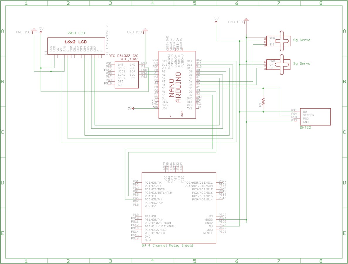
My project consists of:

  1. 20x4 LCD Module
  2. An RTC Module
  3. 2 9g Servo Motors
  4. A DHT22 Temperature and Humidity Sensor
  5. A 4 Channel Relay Shield to Control a 120 volt line and a 12 volt line


My plan is to provide a 5v line for the Arduino itself, a 5v line for the other 5v components, a 12v line, and a 120v line. I plan on using an Arduino Nano in the project so my Mega will still be available afterwards.


So if anyone has the time and is willing to look over the wiring diagram real quick, I'd sure appreciate any feedback or suggestions for improvement. Thanks.


image

  • Sign in to reply
  • Cancel

Top Replies

  • Robert Peter Oakes
    Robert Peter Oakes over 10 years ago +3
    Double check your connections for SDL and SCL to the RTC, you may find it should be A4 and A5 (On an UNO and many other arduinos), then on the mega typically pin 20, 21, not A0, A1 here is a great pinout…
  • Robert Peter Oakes
    Robert Peter Oakes over 10 years ago +2
    SAFETY ISSUE HERE !!! DANGER The Arduino Sheild is NOT ment to handle mains voltages. Like so many other projects we have helped with or provided feedback on this community, the use of a Sheild to directly…
  • Workshopshed
    Workshopshed over 10 years ago in reply to Robert Peter Oakes +2
    A very valid point Peter, I agree, don't use that shield for mains voltages. There's lots of exposed metal on the shield which would be in close proximity to the Arduino (and user). The design of the board…
Parents
  • Robert Peter Oakes
    Robert Peter Oakes over 10 years ago

    SAFETY ISSUE HERE !!! DANGER image


    The Arduino Sheild is NOT ment to handle mains voltages. Like so many other projects we have helped with or provided feedback on this community, the use of a Sheild to directly control mains is just plainly a BAD idea


    Even though the relays on the sheild are rated at mains and several amps, the circuit board, the fact it is pluged into the Arduino and people are so used to handling a powered ardiono like it was a toy all adds up to a disaster waiting to happen... a fatal one


    the sheild you linked in does not specify what it will handle but it is pretty safe to say a good comparison would be the Raspberry PI Digital Board.


    As a general rule, this kind of board is limited to switching about 24V maximum. If you want to switch MAINS, 120V or 240, you need to get a much more appropriate relay and mounting. ie a solid state relay like this

    image

    that should be put in a seperate and secure box with low voltage on one side far away from the mains side, there are loads of other CODE and general safety issues to also consider so get help from a qualified person if needed,


    Switching 12 or 24 volt AC loads or DC LED lighting with the sheild is perfectly OK but not mains.

    • Cancel
    • Vote Up +2 Vote Down
    • Sign in to reply
    • Cancel
Reply
  • Robert Peter Oakes
    Robert Peter Oakes over 10 years ago

    SAFETY ISSUE HERE !!! DANGER image


    The Arduino Sheild is NOT ment to handle mains voltages. Like so many other projects we have helped with or provided feedback on this community, the use of a Sheild to directly control mains is just plainly a BAD idea


    Even though the relays on the sheild are rated at mains and several amps, the circuit board, the fact it is pluged into the Arduino and people are so used to handling a powered ardiono like it was a toy all adds up to a disaster waiting to happen... a fatal one


    the sheild you linked in does not specify what it will handle but it is pretty safe to say a good comparison would be the Raspberry PI Digital Board.


    As a general rule, this kind of board is limited to switching about 24V maximum. If you want to switch MAINS, 120V or 240, you need to get a much more appropriate relay and mounting. ie a solid state relay like this

    image

    that should be put in a seperate and secure box with low voltage on one side far away from the mains side, there are loads of other CODE and general safety issues to also consider so get help from a qualified person if needed,


    Switching 12 or 24 volt AC loads or DC LED lighting with the sheild is perfectly OK but not mains.

    • Cancel
    • Vote Up +2 Vote Down
    • Sign in to reply
    • Cancel
Children
  • Workshopshed
    Workshopshed over 10 years ago in reply to Robert Peter Oakes

    A very valid point Peter, I agree, don't use that shield for mains voltages.


    There's lots of exposed metal on the shield which would be in close proximity to the Arduino (and user). The design of the board puts the switched voltages very close to the pins of the shield. If you look at the SSR, that has significantly higher separation between the low and high voltages.

    If you look at the SSR above or this board from Sparkfun, you can see how the separation is might wider. https://www.sparkfun.com/products/10684

    • Cancel
    • Vote Up +2 Vote Down
    • Sign in to reply
    • Cancel
  • dukeofmarshall
    dukeofmarshall over 10 years ago in reply to Workshopshed

    Thanks for the input guys. That's the reason I wanted to run this by people who knew what they were doing first.


    So if I understand you guys correctly, the danger comes from possibly touching the exposed relay with the 120 volts and also a danger to the Arduino. Not sure if it helps or not, but the final device will be one that has one cord and only plugged in when being used. Also, I planned on using a separate 5v line for the relay shield itself instead of pulling power from the arduino and only hooking up two control lines from the arduino to the relay shield. And finally I had planned on placing all the boards, including the rtc, flat and beside each other instead of stacking them like I've seen some shields placed.


    So with all that in mind and maybe a separate cover for the relay shield, would that change things in your mind or would the same advice and dangers remain?

    • Cancel
    • Vote Up 0 Vote Down
    • Sign in to reply
    • Cancel
  • Robert Peter Oakes
    Robert Peter Oakes over 10 years ago in reply to dukeofmarshall

    What is it you want to control with the relay board (The Mains stuff)


    Peter

    • Cancel
    • Vote Up 0 Vote Down
    • Sign in to reply
    • Cancel
  • Workshopshed
    Workshopshed over 10 years ago in reply to dukeofmarshall

    Todd, for me the issues with using that specific relay shield are:

    • A Peter mentioned, there's an expectation that shields are safe to handle
    • Is the complete system rated for the load (Peter's question?)
    • The close proximity of relay 4's outputs and the low voltage pins
    • Support of the board, if you attach it with 3 mounting screws does it provide adequate support for the screw terminals. Will the board crack/tracks break whilst you are fitting the cabling.


    Other things to think about when building such a project, this is not an exhaustive list but should help you make a safe project.

        1. Is there anything conductive (metal screws etc) that connects the outside of the case to the inside.
        2. Are there any large holes that a finger would fit into? Would that finger touch live parts?
        3. Are there any small holes that a screwdriver would fit into? Would that touch live parts?
        4. Are your cables properly strain relieved? One good way to handle that is to use IEC socket, that avoids the issue of cable strain relief. Although see point 1 about screws/bolts etc. You can also heatshrink or boot these sockets so that the live parts are not accessible.
          image
        5. In the case of a short or problem with the load, is there some form of protection such as a fuse?
        6. Does there need to be some kind of suppression on the relays to stop arcing of the contacts or radio interference? (load dependant)
        7. Is your cabling rated for the load (and higher rated that the protection device) e.g. 5A cables, 3A fuse.
        8. How will you test it safely?
    • Cancel
    • Vote Up +1 Vote Down
    • Sign in to reply
    • Cancel
  • dukeofmarshall
    dukeofmarshall over 10 years ago in reply to Robert Peter Oakes

    I'll be using one of the relays to control a 12v CPU fan and the second relay I'll be using to control a standard 120v CFL light bulb as a heat source. I'm going to need to maintain a temperature of about 95-100 degrees Fahrenheit.

    • Cancel
    • Vote Up 0 Vote Down
    • Sign in to reply
    • Cancel
  • Workshopshed
    Workshopshed over 10 years ago in reply to dukeofmarshall

    Are you making an egg hatcher? I can't imagine that a 120v compact fluorescent lamp puts out much heat, why not use some 12v halogen lights as a heat source?

    • Cancel
    • Vote Up +1 Vote Down
    • Sign in to reply
    • Cancel
  • dukeofmarshall
    dukeofmarshall over 10 years ago in reply to Workshopshed

    Andy,

    Thanks for responding. I'll try to answer your questions in order.


    1. No, nothing to connect the power/control box to the outside. Nothing metallic/conductive anyways except the wires going into and out of it. But they'll be coated or insulated from the factory anyways.
    2. I hadn't planned on any large holes that things could fit into the power/control box. Though I'm not sure if ventilation will be needed for that yet. Would that be a good idea to add to it?
    3. Same as 2
    4. Yes, they will be. I always believe in proper strain relief and contingency.
    5. I hadn't previously planned on putting in any fuse or breaker, but now that you mention it that'd probably be a good idea.
    6. Not sure what you mean, but I had planned on insulating the top of the screw terminals with electrical tape or something.
    7. Oh yeah, plenty of wiggle room there.
    8. Visual inspection and multimeter inspection of various points.
    • Cancel
    • Vote Up 0 Vote Down
    • Sign in to reply
    • Cancel
  • dukeofmarshall
    dukeofmarshall over 10 years ago in reply to Workshopshed

    Andy,

    Yeah, it's an automated incubator. I thought that should be something I could use in real life and would be a fairly straight forward project to get me started with.


    So a 12v halogen would produce the needed heat?

    • Cancel
    • Vote Up +1 Vote Down
    • Sign in to reply
    • Cancel
  • Workshopshed
    Workshopshed over 10 years ago in reply to dukeofmarshall

    Hi Todd, I'd not intended those to be questions, just food for thought whilst you are designing / building it.


    On point 6, when relay contacts are very close there might be a spark that jumps the gap, this causes damage to the contacts and radio interference. Look up snubber circuits or arc suppression.


    I believe that you should be able to get lower voltage lamp that produces heat. Halogens definitely put out quite a lot but there might be other options that work better in this case, there's definitely egg people using halogens (from my limited googling). That would resolve your high voltage issue.

    • Cancel
    • Vote Up +1 Vote Down
    • Sign in to reply
    • Cancel
element14 Community

element14 is the first online community specifically for engineers. Connect with your peers and get expert answers to your questions.

  • Members
  • Learn
  • Technologies
  • Challenges & Projects
  • Products
  • Store
  • About Us
  • Feedback & Support
  • FAQs
  • Terms of Use
  • Privacy Policy
  • Legal and Copyright Notices
  • Sitemap
  • Cookies

An Avnet Company © 2025 Premier Farnell Limited. All Rights Reserved.

Premier Farnell Ltd, registered in England and Wales (no 00876412), registered office: Farnell House, Forge Lane, Leeds LS12 2NE.

ICP 备案号 10220084.

Follow element14

  • X
  • Facebook
  • linkedin
  • YouTube