element14 Community
element14 Community
    Register Log In
  • Site
  • Search
  • Log In Register
  • About Us
  • Community Hub
    Community Hub
    • What's New on element14
    • Feedback and Support
    • Benefits of Membership
    • Personal Blogs
    • Members Area
    • Achievement Levels
  • Learn
    Learn
    • Ask an Expert
    • eBooks
    • element14 presents
    • Learning Center
    • Tech Spotlight
    • STEM Academy
    • Webinars, Training and Events
    • Learning Groups
  • Technologies
    Technologies
    • 3D Printing
    • FPGA
    • Industrial Automation
    • Internet of Things
    • Power & Energy
    • Sensors
    • Technology Groups
  • Challenges & Projects
    Challenges & Projects
    • Design Challenges
    • element14 presents Projects
    • Project14
    • Arduino Projects
    • Raspberry Pi Projects
    • Project Groups
  • Products
    Products
    • Arduino
    • Avnet Boards Community
    • Dev Tools
    • Manufacturers
    • Multicomp Pro
    • Product Groups
    • Raspberry Pi
    • RoadTests & Reviews
  • Store
    Store
    • Visit Your Store
    • Choose another store...
      • Europe
      •  Austria (German)
      •  Belgium (Dutch, French)
      •  Bulgaria (Bulgarian)
      •  Czech Republic (Czech)
      •  Denmark (Danish)
      •  Estonia (Estonian)
      •  Finland (Finnish)
      •  France (French)
      •  Germany (German)
      •  Hungary (Hungarian)
      •  Ireland
      •  Israel
      •  Italy (Italian)
      •  Latvia (Latvian)
      •  
      •  Lithuania (Lithuanian)
      •  Netherlands (Dutch)
      •  Norway (Norwegian)
      •  Poland (Polish)
      •  Portugal (Portuguese)
      •  Romania (Romanian)
      •  Russia (Russian)
      •  Slovakia (Slovak)
      •  Slovenia (Slovenian)
      •  Spain (Spanish)
      •  Sweden (Swedish)
      •  Switzerland(German, French)
      •  Turkey (Turkish)
      •  United Kingdom
      • Asia Pacific
      •  Australia
      •  China
      •  Hong Kong
      •  India
      •  Korea (Korean)
      •  Malaysia
      •  New Zealand
      •  Philippines
      •  Singapore
      •  Taiwan
      •  Thailand (Thai)
      • Americas
      •  Brazil (Portuguese)
      •  Canada
      •  Mexico (Spanish)
      •  United States
      Can't find the country/region you're looking for? Visit our export site or find a local distributor.
  • Translate
  • Profile
  • Settings
Arduino
  • Products
  • More
Arduino
Arduino Forum Electrical questions about my robot
  • Blog
  • Forum
  • Documents
  • Quiz
  • Events
  • Polls
  • Files
  • Members
  • Mentions
  • Sub-Groups
  • Tags
  • More
  • Cancel
  • New
Join Arduino to participate - click to join for free!
Actions
  • Share
  • More
  • Cancel
Forum Thread Details
  • State Verified Answer
  • Replies 26 replies
  • Answers 17 answers
  • Subscribers 395 subscribers
  • Views 1793 views
  • Users 0 members are here
  • arduino uno
Related

Electrical questions about my robot

braedan
braedan over 9 years ago

Hello Element14 community,


I have an amateur understanding of dc electronics but there are a few questions that i haven't found any other threads or discussions on. Probably because i do not know the name of the specific topic.

Forgive me if the answer is obvious, but my first question is on current placement. When i look at a solder less breadboard there are two lanes for a positive and negative voltage from a power supply. Say i have an 6v red led drawing 30ma from the power supply, but is connected to the power supply from the middle of the breadboards power lanes. Now if there is a 6v dc motor connected to the end of the power lanes and is drawing 1.5 amps or so, does the high current affect the led in front of the motor? again: there are 1.5 amps going across the power lanes to the motor at the end, but there is a small led drawing much less current before the motor from the same power source.


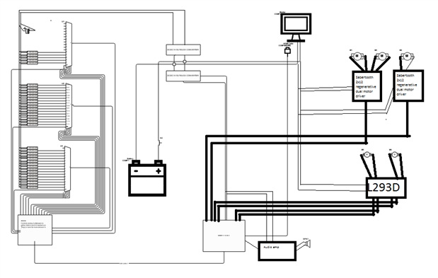
My second question is about capacitors. I have an array of Sharp (brand) Infrared distance sensors that operate at 5 volts and draw current in sharp bursts rated at around 30-60ma on average. I am planning on wiring all 37 of them to 3, 16 channel multiplexers connected to and Arduino uno that will then read the sensors analog output. (Multiplexer i will be using is the cd74hc4067). I have two questions on this topic, both of them about power connectivity. My first question is about the sensors. On a the sensors website and data sheet they both strongly recommend the use of some sort of capacitor to smooth things out. Please look at the picture attached and help me find the best places to add this extra circuitry. Please keep in mind that the S in the image is the Sharp infrared distance sensor and there are actually 37 sensors and not 3. Second is about the power it self. I was told that the sensor array would take little over 1.5 amps and to be safe i should have a power supply that can supply double the amount of current needed. The problem is that i don't actually need a power supply because i will be running this off a 12v lead acid battery. I'm not sure how to build a voltage regulator that can supply this amount of current (3 amps), if a voltage regulator is what i need. later I found this UBEC DC/DC Step-Down (Buck) Converter 5v @ 3a output on Adafruit but yet again i'm skeptical if it will properly power everything.


P.S. - Could a 12v 7aH lead acid battery (specifically this one: https://www.amazon.com/ExpertPower-EXP1270-Rechargeable-Lead-Battery/dp/B003S1RQ2S/ref=sr_1_3?ie=UTF8&qid=1468962932&sr=… )

power this arduino sensor array? Specifically how much am i able to draw from this battery? In the future i plan on building a large robot and i need a battery that will be able to power this sensor array, 3 sub 100watt 24v DC motors, 2 small 24v DC gear motors,a raspberry pi 2b and a 12v dc VGA monitor. I know its allot but they all wont be running at once (mainly the motors) and i also know that i can increase the battery capacity by wiring two or more together in parallel (please correct me if i'm wrong). I'm just asking if this lead acid battery type can discharge the required amount of power with out any battery problems, i don't what any battery fires or an explosion.


Please write me back and helpful links or answers to my questions!

Thank you for your time!

Attachments:
image
  • Sign in to reply
  • Cancel

Top Replies

  • DAB
    DAB over 9 years ago +3 suggested
    Hi Braedan, You have an ambitious plan and I highly suggest you find someone local to help you with the electronics. Most drive circuits use either a constant current device and or a nice capacitor bank…
  • billpenner
    billpenner over 9 years ago in reply to jw0752 +2 suggested
    just a few thoughts, Braedan: You should definitely use a buck converter for the circuits other than the motors. Since the motors will be 24 volts and other circuits will be 5 Volts, the basic power supply…
  • michaelwylie
    michaelwylie over 9 years ago +2 suggested
    Q1 - Ideally one load does not effect the other. In reality many things can happen. For instance, in your example provided, the motor, or any inductive load, will produce an EMF that will likely feedback…
Parents
  • braedan
    0 braedan over 9 years ago

    Hello!


    Thank you all for acknowledging my post, and I am very sorry for my incompleteness and professionalism. I am currently working on a cuircuit diagram that I will post ASAP.

    To fill in any gaps I left out I'll try to tell you all about my current robotics project. I have received a large broken medical telepresence robot from a friends parent who works at the robotics company. After a i confirmed that the bot was indeed busted I began striping it down till it was just the motors and sensors left. Im now planning on putting in my own hardware to control the chassis. The robots features are as follows:

    a vga monitor, two cameras with the same output (some wires I dont understand), two 24v motors with mysterious 5 wire encoder (power to the motor isn't applied through the encoder), There are 37 Sharp brand IR distance sensors That are placed all around the base, 1 large speaker, 1 knob (probably a rotary encoder that used to be for controlling the volume), on the bottom are 3 larger 24v dc motors with the same motor encoders mentioned above. The three motors move the robot using holonimic drive. It has been quite the job so far. I'm planning on using a Raspberry pi 2 for the brains, connected to a arduino providing it with sensor data over a usb cable. The raspberry pi will control the 3 motor drivers used and needed. Two sabertooth 2x12 (dual) motor drivers for the bottom 3 motors and a L293D dual h bridge to control the top two motors in the robots neck. I now need help on how to effectivly power all these individual components off a single battery with out damaging anything.

    Thank you for all your help!

    P.s. I also need help in understanding the pinout of the motor encoders because that information is crucial for the development of this robot. I also would like to know the pinout of the top two cameras though it is not entirely necessary because I will soon replace them both with either a raspberry pi camera module or an xbox 360 Kinect 3d sensor/camera because it provides RGBD data witch could be useful.

    thank you once again!

    • Cancel
    • Vote Up +1 Vote Down
    • Sign in to reply
    • Verify Answer
    • Reject Answer
    • Cancel
  • braedan
    0 braedan over 9 years ago in reply to braedan

    Pictures are on there way!

    • Cancel
    • Vote Up 0 Vote Down
    • Sign in to reply
    • Verify Answer
    • Cancel
  • braedan
    0 braedan over 9 years ago in reply to braedan

    OK, here are the manufacturers images of the robot and the circuit diagram, i will say before hand that it was my first attempt at using this king of computer program and towards the end it didn't let me do what i needed so i just drew over it using paint. Also the program did a terrible job exporting the image, i am very sorry and i am very mad at the program. The robot is the RP-7 medical telepresence robot by the way. imageimageimageimage

    you can see in the pictures above of a fully assembled RP-7. So far i have removed (nearly) all open pannels and completely removed its, well, everything exempt motors sensors and a display. Soon i will remove the two cameras you see placed above the screen. I should also mention that since there is a reference available, the two small 24v dc motors control the up down and side to side (x,y) movement of screen. from now on i will reference it as the head. And quite obviously there are three large 24v dc motors on the bottom. in a triangle formation, the on at the tip goes side to side, while the two in the back go forward and back and actually drive it forwards. the one in the front is just for turning and steering. I hope you see why i need to control 37 ir sensors now: all the black rectangles are sensors. In the circuit diagram i intentionally left out the ceramic capacitors that go with each IR sensor because it was to tight of a fit. also i haven't really planned out where i would put the audio amp so i put it where you see now. I am also thinking that there should be some more filtering going on, especially by the monitor. Please correct me if i'm wrong (which i usually am).


    Thank you! - Braedan

    • Cancel
    • Vote Up +1 Vote Down
    • Sign in to reply
    • Verify Answer
    • Reject Answer
    • Cancel
  • braedan
    0 braedan over 9 years ago in reply to braedan

    Here are some more pictures i took of the bot.imageimageimageimageimageimage

    • Cancel
    • Vote Up +1 Vote Down
    • Sign in to reply
    • Verify Answer
    • Reject Answer
    • Cancel
  • DAB
    0 DAB over 9 years ago in reply to braedan

    Great pictures Braedan.


    OK, the IR sensors just pickup anyone or anything that approaches the robot base.


    I suspect they are set up for about 10 cm detection range.


    The motors should provide you with a nice smooth platform on which to build your robot.


    I suspect that the motors are just DC with encoders.  You should have two main power wires and then two or four smaller encoder wires.


    The encoders are probably quadrature output to give you a number of pulses for each wheel rotation plus the encoding provides plus or minus direction indication.


    DAB

    • Cancel
    • Vote Up 0 Vote Down
    • Sign in to reply
    • Verify Answer
    • Reject Answer
    • Cancel
Reply
  • DAB
    0 DAB over 9 years ago in reply to braedan

    Great pictures Braedan.


    OK, the IR sensors just pickup anyone or anything that approaches the robot base.


    I suspect they are set up for about 10 cm detection range.


    The motors should provide you with a nice smooth platform on which to build your robot.


    I suspect that the motors are just DC with encoders.  You should have two main power wires and then two or four smaller encoder wires.


    The encoders are probably quadrature output to give you a number of pulses for each wheel rotation plus the encoding provides plus or minus direction indication.


    DAB

    • Cancel
    • Vote Up 0 Vote Down
    • Sign in to reply
    • Verify Answer
    • Reject Answer
    • Cancel
Children
  • braedan
    0 braedan over 9 years ago in reply to DAB

    Thanks dab,


    the motors are DC. Are the two main power wires you mentioned to controll the motor or power the encoder?

    • Cancel
    • Vote Up 0 Vote Down
    • Sign in to reply
    • Verify Answer
    • Cancel
  • DAB
    0 DAB over 9 years ago in reply to braedan

    If you only have two wires, then they are just for the motor.


    You have some excellently designed gear reduction for the motors.


    They should provide you with a wide range of control.


    Plus the construction of the whole base is well engineered.  You have a really well made base for a robot.


    Nice score.


    DAB

    • Cancel
    • Vote Up 0 Vote Down
    • Sign in to reply
    • Verify Answer
    • Reject Answer
    • Cancel
element14 Community

element14 is the first online community specifically for engineers. Connect with your peers and get expert answers to your questions.

  • Members
  • Learn
  • Technologies
  • Challenges & Projects
  • Products
  • Store
  • About Us
  • Feedback & Support
  • FAQs
  • Terms of Use
  • Privacy Policy
  • Legal and Copyright Notices
  • Sitemap
  • Cookies

An Avnet Company © 2025 Premier Farnell Limited. All Rights Reserved.

Premier Farnell Ltd, registered in England and Wales (no 00876412), registered office: Farnell House, Forge Lane, Leeds LS12 2NE.

ICP 备案号 10220084.

Follow element14

  • X
  • Facebook
  • linkedin
  • YouTube