element14 Community
element14 Community
    Register Log In
  • Site
  • Search
  • Log In Register
  • About Us
  • Community Hub
    Community Hub
    • What's New on element14
    • Feedback and Support
    • Benefits of Membership
    • Personal Blogs
    • Members Area
    • Achievement Levels
  • Learn
    Learn
    • Ask an Expert
    • eBooks
    • element14 presents
    • Learning Center
    • Tech Spotlight
    • STEM Academy
    • Webinars, Training and Events
    • Learning Groups
  • Technologies
    Technologies
    • 3D Printing
    • FPGA
    • Industrial Automation
    • Internet of Things
    • Power & Energy
    • Sensors
    • Technology Groups
  • Challenges & Projects
    Challenges & Projects
    • Design Challenges
    • element14 presents Projects
    • Project14
    • Arduino Projects
    • Raspberry Pi Projects
    • Project Groups
  • Products
    Products
    • Arduino
    • Avnet Boards Community
    • Dev Tools
    • Manufacturers
    • Multicomp Pro
    • Product Groups
    • Raspberry Pi
    • RoadTests & Reviews
  • Store
    Store
    • Visit Your Store
    • Choose another store...
      • Europe
      •  Austria (German)
      •  Belgium (Dutch, French)
      •  Bulgaria (Bulgarian)
      •  Czech Republic (Czech)
      •  Denmark (Danish)
      •  Estonia (Estonian)
      •  Finland (Finnish)
      •  France (French)
      •  Germany (German)
      •  Hungary (Hungarian)
      •  Ireland
      •  Israel
      •  Italy (Italian)
      •  Latvia (Latvian)
      •  
      •  Lithuania (Lithuanian)
      •  Netherlands (Dutch)
      •  Norway (Norwegian)
      •  Poland (Polish)
      •  Portugal (Portuguese)
      •  Romania (Romanian)
      •  Russia (Russian)
      •  Slovakia (Slovak)
      •  Slovenia (Slovenian)
      •  Spain (Spanish)
      •  Sweden (Swedish)
      •  Switzerland(German, French)
      •  Turkey (Turkish)
      •  United Kingdom
      • Asia Pacific
      •  Australia
      •  China
      •  Hong Kong
      •  India
      •  Korea (Korean)
      •  Malaysia
      •  New Zealand
      •  Philippines
      •  Singapore
      •  Taiwan
      •  Thailand (Thai)
      • Americas
      •  Brazil (Portuguese)
      •  Canada
      •  Mexico (Spanish)
      •  United States
      Can't find the country/region you're looking for? Visit our export site or find a local distributor.
  • Translate
  • Profile
  • Settings
Arduino
  • Products
  • More
Arduino
Arduino Forum External button interface design help and review
  • Blog
  • Forum
  • Documents
  • Quiz
  • Events
  • Polls
  • Files
  • Members
  • Mentions
  • Sub-Groups
  • Tags
  • More
  • Cancel
  • New
Join Arduino to participate - click to join for free!
Actions
  • Share
  • More
  • Cancel
Forum Thread Details
  • State Verified Answer
  • Replies 3 replies
  • Answers 1 answer
  • Subscribers 391 subscribers
  • Views 472 views
  • Users 0 members are here
  • pc interface
  • help_needed
  • pcb
  • prototyping
  • arduino
Related

External button interface design help and review

chrisdadragon
chrisdadragon over 7 years ago

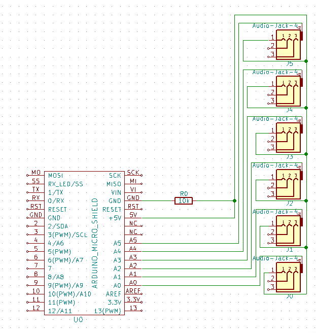
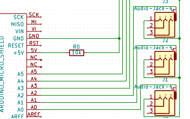
Hi, I made this schematic for my project of connecting multiple push buttons via TS/TRS/TRRS (mic jack) don’t ask why i didn’t just use TS lets just say check before you buyimage. 1 thing im not sure about is the 10k pull-up resistor do I only need that one or 5 (one for each button). If I made a mistake can you tell me about it, im very new to this so any feedback would be appreciated. btw I use kicad.


image

  • Sign in to reply
  • Cancel

Top Replies

  • shabaz
    shabaz over 7 years ago +4 verified
    Hi Chris, For accepting switch inputs, your aim is to have a scheme where each input pin on the Arduino sees either 0V (GND) or 5V. It doesn't matter which one, but the aim is to have it become the opposite…
  • shabaz
    shabaz over 7 years ago in reply to chrisdadragon +1 suggested
    Hi Chris, Just build the circuit shown earlier (the one in my previous response), which uses one resistor, and one switch. You can connect the top junction to 5V, and the bottom junction to GND. The center…
Parents
  • shabaz
    0 shabaz over 7 years ago

    Hi Chris,


    For accepting switch inputs, your aim is to have a scheme where each input pin on the Arduino sees either 0V (GND) or 5V. It doesn't matter which one, but the aim is to have it become the opposite selection whenever the button is pressed.


    So, for example A0 could be at +5V, but when the button is pressed, it could become 0V. And so on for the other switches and inputs.


    A switch on its own can't (generally) work, because it just has metal conductors inside it, and if you short 5V to GND, then lots of current flows and damages the switch.


    The resistor is used to reduce current. Think of a series circuit, consisting of (in this order) +5V, Resistor, Switch, GND.

    Now if you use a multimeter, stick one end on GND, and the other end at the junction between the resistor and the switch, you'll see that the voltage measured is +5V. But, when the switch is pressed, the voltage measured is 0V because the switch has very low resistance (almost zero ohms) and so the junction voltage becomes close to 0V.


    So, if your Arduino input (A0) was connected to that junction, then it too would see +5V normally, until the switch is pressed.


    See here for an example. It isn't for an Arduino, so ignore the labels. You would build this circuit for each input, i.e. as many resistors as there are switches.


    image

    • Cancel
    • Vote Up +4 Vote Down
    • Sign in to reply
    • Verify Answer
    • Reject Answer
    • Cancel
  • chrisdadragon
    0 chrisdadragon over 7 years ago in reply to shabaz

    ok so i did this but I don't really understand what I need to do, ive read your message many times but still haven't understood it could you try to explain it differently sorry I am awful at circuits. when you say "as many resistors as there are switches" i can't figure out how to do that as there is no way I can see to connect ground and +5 and the pinimage

    • Cancel
    • Vote Up 0 Vote Down
    • Sign in to reply
    • Verify Answer
    • Cancel
  • shabaz
    0 shabaz over 7 years ago in reply to chrisdadragon

    Hi Chris,


    Just build the circuit shown earlier (the one in my previous response), which uses one resistor, and one switch. You can connect the top junction to 5V, and the bottom junction to GND.


    The center junction (marked GPIO) goes to A0 on your Arduino.


    Test it, run your code, and you'll see that the Arduino code sees the input going low when the switch is pressed.


    Now, to replicate this to multiple switches, just repeat the entire circuit. For each repeated circuit, connect the top to 5V, and the bottom to GND. Connect the junction to A1 for the next one, and A2 for the third one, and so on.


    Since you're repeating the circuit, you need as many resistors as you have switches.


    If you wish to understand the circuit (important, so you feel confident in what you're doing), you can see that when the switch is not pressed, +5V is available at the GPIO pin through the resistor. But, when the switch is pressed, then the switch has less resistance than the resistor. It will be almost zero ohms, so electrically this is the same as the switch being replaced with a wire shorting the connections. That means that GND (0V) is seen at the GPIO connection.


    This is known as a potential divider, where the bottom part of the circuit can be seen as a very high (near infinite) resistance when the switch is not pressed, and as a very low (near zero) resistance when the switch is pressed. If you google 'potential divider' it will be explained.

    • Cancel
    • Vote Up +1 Vote Down
    • Sign in to reply
    • Verify Answer
    • Reject Answer
    • Cancel
Reply
  • shabaz
    0 shabaz over 7 years ago in reply to chrisdadragon

    Hi Chris,


    Just build the circuit shown earlier (the one in my previous response), which uses one resistor, and one switch. You can connect the top junction to 5V, and the bottom junction to GND.


    The center junction (marked GPIO) goes to A0 on your Arduino.


    Test it, run your code, and you'll see that the Arduino code sees the input going low when the switch is pressed.


    Now, to replicate this to multiple switches, just repeat the entire circuit. For each repeated circuit, connect the top to 5V, and the bottom to GND. Connect the junction to A1 for the next one, and A2 for the third one, and so on.


    Since you're repeating the circuit, you need as many resistors as you have switches.


    If you wish to understand the circuit (important, so you feel confident in what you're doing), you can see that when the switch is not pressed, +5V is available at the GPIO pin through the resistor. But, when the switch is pressed, then the switch has less resistance than the resistor. It will be almost zero ohms, so electrically this is the same as the switch being replaced with a wire shorting the connections. That means that GND (0V) is seen at the GPIO connection.


    This is known as a potential divider, where the bottom part of the circuit can be seen as a very high (near infinite) resistance when the switch is not pressed, and as a very low (near zero) resistance when the switch is pressed. If you google 'potential divider' it will be explained.

    • Cancel
    • Vote Up +1 Vote Down
    • Sign in to reply
    • Verify Answer
    • Reject Answer
    • Cancel
Children
No Data
element14 Community

element14 is the first online community specifically for engineers. Connect with your peers and get expert answers to your questions.

  • Members
  • Learn
  • Technologies
  • Challenges & Projects
  • Products
  • Store
  • About Us
  • Feedback & Support
  • FAQs
  • Terms of Use
  • Privacy Policy
  • Legal and Copyright Notices
  • Sitemap
  • Cookies

An Avnet Company © 2025 Premier Farnell Limited. All Rights Reserved.

Premier Farnell Ltd, registered in England and Wales (no 00876412), registered office: Farnell House, Forge Lane, Leeds LS12 2NE.

ICP 备案号 10220084.

Follow element14

  • X
  • Facebook
  • linkedin
  • YouTube