element14 Community
element14 Community
    Register Log In
  • Site
  • Search
  • Log In Register
  • Community Hub
    Community Hub
    • What's New on element14
    • Feedback and Support
    • Benefits of Membership
    • Personal Blogs
    • Members Area
    • Achievement Levels
  • Learn
    Learn
    • Ask an Expert
    • eBooks
    • element14 presents
    • Learning Center
    • Tech Spotlight
    • STEM Academy
    • Webinars, Training and Events
    • Learning Groups
  • Technologies
    Technologies
    • 3D Printing
    • FPGA
    • Industrial Automation
    • Internet of Things
    • Power & Energy
    • Sensors
    • Technology Groups
  • Challenges & Projects
    Challenges & Projects
    • Design Challenges
    • element14 presents Projects
    • Project14
    • Arduino Projects
    • Raspberry Pi Projects
    • Project Groups
  • Products
    Products
    • Arduino
    • Avnet & Tria Boards Community
    • Dev Tools
    • Manufacturers
    • Multicomp Pro
    • Product Groups
    • Raspberry Pi
    • RoadTests & Reviews
  • About Us
    About the element14 Community
  • Store
    Store
    • Visit Your Store
    • Choose another store...
      • Europe
      •  Austria (German)
      •  Belgium (Dutch, French)
      •  Bulgaria (Bulgarian)
      •  Czech Republic (Czech)
      •  Denmark (Danish)
      •  Estonia (Estonian)
      •  Finland (Finnish)
      •  France (French)
      •  Germany (German)
      •  Hungary (Hungarian)
      •  Ireland
      •  Israel
      •  Italy (Italian)
      •  Latvia (Latvian)
      •  
      •  Lithuania (Lithuanian)
      •  Netherlands (Dutch)
      •  Norway (Norwegian)
      •  Poland (Polish)
      •  Portugal (Portuguese)
      •  Romania (Romanian)
      •  Russia (Russian)
      •  Slovakia (Slovak)
      •  Slovenia (Slovenian)
      •  Spain (Spanish)
      •  Sweden (Swedish)
      •  Switzerland(German, French)
      •  Turkey (Turkish)
      •  United Kingdom
      • Asia Pacific
      •  Australia
      •  China
      •  Hong Kong
      •  India
      •  Japan
      •  Korea (Korean)
      •  Malaysia
      •  New Zealand
      •  Philippines
      •  Singapore
      •  Taiwan
      •  Thailand (Thai)
      •  Vietnam
      • Americas
      •  Brazil (Portuguese)
      •  Canada
      •  Mexico (Spanish)
      •  United States
      Can't find the country/region you're looking for? Visit our export site or find a local distributor.
  • Translate
  • Profile
  • Settings
Arduino
  • Products
  • More
Arduino
Arduino Forum reading AC voltage from an arduino
  • Blog
  • Forum
  • Documents
  • Quiz
  • Events
  • Polls
  • Files
  • Members
  • Mentions
  • Sub-Groups
  • Tags
  • More
  • Cancel
  • New
Join Arduino to participate - click to join for free!
Actions
  • Share
  • More
  • Cancel
Forum Thread Details
  • State Verified Answer
  • Replies 19 replies
  • Answers 3 answers
  • Subscribers 416 subscribers
  • Views 3498 views
  • Users 0 members are here
  • adc
  • low voltage rectifier
Related

reading AC voltage from an arduino

anishkgt
anishkgt over 8 years ago

Hi All,


I am trying to read a few millivolts through the ADC of an Arduino. This is an ac voltage with variable voltage and frequency. There are precision rectifiers like the LT1078 that can rectify the signal to dc but since the signal has variable frequency, opamps cannot handle this. No matter what the slew rate, since the frequency changes the opamp has trouble following that signal.

Well if somebody could prove me wrong and advise a better way to do it.

image


image

  • Sign in to reply
  • Cancel

Top Replies

  • michaelkellett
    michaelkellett over 8 years ago in reply to anishkgt +3 verified
    Your design won't work very well (using an op amp as a rectifier isn't too nice). This is a bit more complicated but will do the job. The amplifier output is biased at about 2.5V. The bias comes from the…
  • michaelkellett
    michaelkellett over 8 years ago in reply to anishkgt +2
    Both your scope traces are showing 200ns per division and a time window of 2.4us in total. This is confirmed by the scope estimate of about 6.5MHz for the ringing frequency which gives about 16 cycles…
  • michaelkellett
    michaelkellett over 8 years ago +1
    Your scope traces suggest that the approximate frequency is around 5MHz and the peak amplitude about 1V. Hard to be sure because the pictures don't show the grid on the scope very well (or even at all…
Parents
  • dougw
    0 dougw over 8 years ago

    It sounds like a pretty interesting challenge - trying to measure an ac current spike.

    I once designed a system to measure spot weld performance using a fiber optic sensor because the previous team has tremendous difficulty getting good results by measuring voltage and current. As Michael mentioned the electric and magnetic fields were just brutal. Also a lot of energy can be going places that don't help the weld.

    Are you trying to measure how strong the weld joint is? What temperature the metal reached? What area was melted? Or just how much energy exited the probe?

    There other ways to measure weld performance as well.

    When you say spot weld, are you referring to a traditional resistance spot weld where it is the resistance of the metal that creates the heat to form the weld?

    Or are you referring to an arc spot weld where the arc generates the heat that melts the metal?

    The reason for asking is there may be easier ways to measure what you really need to know.

    Back to measuring the current spike..

    As you and Michael point out knowing the timing is critical in determining if and how an arduino can help.

    You could increase the voltage by making a one or more turn inductor between your measurement probes, making rectification easier.

    You could also use a transformer to increase measurement voltage, then you just need diodes for rectification and some sort of RC filter.

    You could use an analog integrator circuit to capture the energy in the spike, if it is too fast for an arduino.

    • Cancel
    • Vote Up +1 Vote Down
    • Sign in to reply
    • Verify Answer
    • Reject Answer
    • Cancel
  • anishkgt
    0 anishkgt over 8 years ago in reply to dougw

    Thank you Douglas for taking notice.


    i am designing a Resistance Spot Welder to weld 18650 cells and i just need to measure the current put into the spot. Not sure how many turns and how much thickness to be used. Another transformer would be out of the scope of this project just because limited on the PCB size.


    For i now i will just increase the distance between the tabs and see how things go from there.

    • Cancel
    • Vote Up 0 Vote Down
    • Sign in to reply
    • Verify Answer
    • Cancel
  • anishkgt
    0 anishkgt over 8 years ago in reply to anishkgt

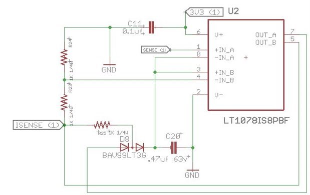
    Initially i was thinking of using this circuit to do this latter figured out that the opamps cannot keep up with the variable voltage and frequency up 9Mhz.

    image


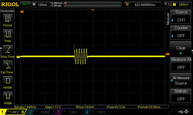
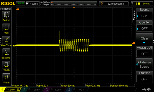
    Now rewound the MOT and took a reading 40cm apart.


    At 110ms

    image


    at 310ms

    image


    I guess the above schematic would work but i was thinking of making it more simple like "detect OFF state of an AC LOAD" suggested by dougw. I would like to learn if there would be a simpler schematic to accomplish this.

    • Cancel
    • Vote Up 0 Vote Down
    • Sign in to reply
    • Verify Answer
    • Cancel
  • michaelkellett
    0 michaelkellett over 8 years ago in reply to anishkgt

    Now your traces look like the real thing !


    You will need to be able to measure the amplitude to the required degree of accuracy within each mains cycle. Arduinos are not brilliant at controlling the rate at which the ADC samples but they can be made to sample fast enough, you want at least 50 samples per mains cycle = 50 * 50 = 2500 samples per second (for 50Hz mains.).


    Using a rectifier isn't going to work here - the rectifier chips or circuit will all have a smoothing cpacitor so that the ripple on the output is not too big, but this smoothing means that the response time of the rectifier will be many cycles of the lowest frequency you want to measure - so a typical welding burst of a few mains cycles will not be measured accurately.


    If you use the ADC in the Arduino to sample the waveform at a reasonable speed you should be able to estimate the amplitude cycle by cycle.


    You'll need a low pass filter to get rid of the high frequency Mhz rubbish when you switch on and off (cut off frequency maybe 250Hz should do) and a level shifter to position the signal in the middle of the Arduino's ADC range.


    The amplitude of the signal in you scope traces  looks suspiciously large -  a typical welding voltage would be maybe 1.5V so dropping 0.5V or so across the current sensor seems a bit much.


    You can make the low pass filter and level shifter using pretty much any rail to rail IO op amps - speed is not going to be a problem. The Microchip parts are cheap and easy to get. The LTC6240 is not ideal because it is faster than you need and does not have rail to rail inputs.


    If you need some help designing the filter and level shifter then let us know. Resist the temptation to AC couple the signal rather than level shift because the  ac coupling will distor the shape of the pulse burst unless the time constant is >> length of burst.


    MK

    • Cancel
    • Vote Up +1 Vote Down
    • Sign in to reply
    • Verify Answer
    • Reject Answer
    • Cancel
  • anishkgt
    0 anishkgt over 8 years ago in reply to michaelkellett

    Thank you michael.


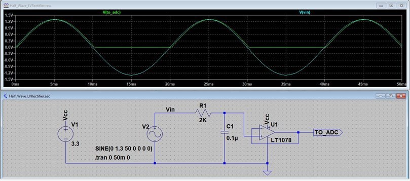
    based on your suggestion i've put up the schematic and simulated it. Looks good to me but am looking something cheaper 7$ for the LT1078.


    image

    here R1 and C1 make up the Low Pass filter. The opamp acts like a follower and a half-wave rectifier.

    Attachments:
    Half_Wave_LVRectifier.asc.zip
    • Cancel
    • Vote Up 0 Vote Down
    • Sign in to reply
    • Verify Answer
    • Cancel
  • michaelkellett
    0 michaelkellett over 8 years ago in reply to anishkgt

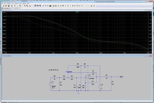
    Your design won't work very well (using an op amp as a rectifier isn't too nice). This is a bit more complicated but will do the job. The amplifier output is biased at about 2.5V. The bias comes from the 5V supply via R6 and R5 so the supply must not be too noisy although C3 does filter it.


    Almost any amp would do for U1, the LTC6240 is just the first that came to hand for simulating - I suggest the Microchip 6281 which comes in PDIP, SOIC or MSOP packages and costs about £0.50.


    This design relies on having a very low DC source impedance so should be OK for this application. There ought to be some decoupling across the supply close to the op amp in real life (100nF ceramic)


    image


    MK

    • Cancel
    • Vote Up +3 Vote Down
    • Sign in to reply
    • Verify Answer
    • Reject Answer
    • Cancel
Reply
  • michaelkellett
    0 michaelkellett over 8 years ago in reply to anishkgt

    Your design won't work very well (using an op amp as a rectifier isn't too nice). This is a bit more complicated but will do the job. The amplifier output is biased at about 2.5V. The bias comes from the 5V supply via R6 and R5 so the supply must not be too noisy although C3 does filter it.


    Almost any amp would do for U1, the LTC6240 is just the first that came to hand for simulating - I suggest the Microchip 6281 which comes in PDIP, SOIC or MSOP packages and costs about £0.50.


    This design relies on having a very low DC source impedance so should be OK for this application. There ought to be some decoupling across the supply close to the op amp in real life (100nF ceramic)


    image


    MK

    • Cancel
    • Vote Up +3 Vote Down
    • Sign in to reply
    • Verify Answer
    • Reject Answer
    • Cancel
Children
  • anishkgt
    0 anishkgt over 8 years ago in reply to michaelkellett

    Thanks i thought all that was required was that the voltage should be followed and omit any negative signal into the Arduino.

    • Cancel
    • Vote Up 0 Vote Down
    • Sign in to reply
    • Verify Answer
    • Cancel
  • anishkgt
    0 anishkgt over 8 years ago in reply to anishkgt

    and yea Complicated indeed.image

    • Cancel
    • Vote Up 0 Vote Down
    • Sign in to reply
    • Verify Answer
    • Cancel
  • michaelkellett
    0 michaelkellett over 8 years ago in reply to anishkgt

    It's not that complicated image

    One op-amp. and some Rs and Cs.

    I was quite pleased with myself in getting the filter and level shifter in one op amp. It  would be better with more attenuation at half the sampling frequency (1.25kHz) but should be OK .


    Please let me know how you get on if you build it.


    MK

    • Cancel
    • Vote Up 0 Vote Down
    • Sign in to reply
    • Verify Answer
    • Cancel
  • anishkgt
    0 anishkgt over 8 years ago in reply to michaelkellett

    Thank you Michael. I am just trying to reduce BOM and cost.


    I've attached the schematic of the PCB that i now had fabricated for testing.Will have to add these and one suggested by dougw as well in my next design. but before that i need to see how this goes. This was something i had used for reference for the current sensing part. my first one did not very well. Components are SMD and without SMD reflow oven and just with a cooking hot plate temp fluctuated and some components were damaged.

    • Cancel
    • Vote Up 0 Vote Down
    • Sign in to reply
    • Verify Answer
    • Cancel
  • anishkgt
    0 anishkgt over 8 years ago in reply to anishkgt

    I just simulated your design and i can see for any rise in the ac signal has significant rise in the output voltage. Should be easily detectable by an arduino.


    but a few doubts, what does R3 to R8 and C1 to C4 do in your design ? i am just learning to put Opamps into use. Took me a while to make sense out of what inverting and non-inverting terms actually meant.image

    • Cancel
    • Vote Up 0 Vote Down
    • Sign in to reply
    • Verify Answer
    • Cancel
  • anishkgt
    0 anishkgt over 8 years ago in reply to michaelkellett

    Hi @michaelkellett I was online at digikey but for some reason i am unable to find the parts for a Contact sense circuit that one of the users here had suggested. Would it be possible to use your circuit there ? The only problem is that the circuit would be exposed to 240vac and that should be suppressed somehow. Would it ok to use an opto-isolator in series to your circuit and disable it from an arduino.

    • Cancel
    • Vote Up 0 Vote Down
    • Sign in to reply
    • Verify Answer
    • Cancel
element14 Community

element14 is the first online community specifically for engineers. Connect with your peers and get expert answers to your questions.

  • Members
  • Learn
  • Technologies
  • Challenges & Projects
  • Products
  • Store
  • About Us
  • Feedback & Support
  • FAQs
  • Terms of Use
  • Privacy Policy
  • Legal and Copyright Notices
  • Sitemap
  • Cookies

An Avnet Company © 2026 Premier Farnell Limited. All Rights Reserved.

Premier Farnell Ltd, registered in England and Wales (no 00876412), registered office: Farnell House, Forge Lane, Leeds LS12 2NE.

Follow element14

  • X
  • Facebook
  • linkedin
  • YouTube