element14 Community
element14 Community
    Register Log In
  • Site
  • Search
  • Log In Register
  • Community Hub
    Community Hub
    • What's New on element14
    • Feedback and Support
    • Benefits of Membership
    • Personal Blogs
    • Members Area
    • Achievement Levels
  • Learn
    Learn
    • Ask an Expert
    • eBooks
    • element14 presents
    • Learning Center
    • Tech Spotlight
    • STEM Academy
    • Webinars, Training and Events
    • Learning Groups
  • Technologies
    Technologies
    • 3D Printing
    • FPGA
    • Industrial Automation
    • Internet of Things
    • Power & Energy
    • Sensors
    • Technology Groups
  • Challenges & Projects
    Challenges & Projects
    • Design Challenges
    • element14 presents Projects
    • Project14
    • Arduino Projects
    • Raspberry Pi Projects
    • Project Groups
  • Products
    Products
    • Arduino
    • Avnet & Tria Boards Community
    • Dev Tools
    • Manufacturers
    • Multicomp Pro
    • Product Groups
    • Raspberry Pi
    • RoadTests & Reviews
  • About Us
  • Store
    Store
    • Visit Your Store
    • Choose another store...
      • Europe
      •  Austria (German)
      •  Belgium (Dutch, French)
      •  Bulgaria (Bulgarian)
      •  Czech Republic (Czech)
      •  Denmark (Danish)
      •  Estonia (Estonian)
      •  Finland (Finnish)
      •  France (French)
      •  Germany (German)
      •  Hungary (Hungarian)
      •  Ireland
      •  Israel
      •  Italy (Italian)
      •  Latvia (Latvian)
      •  
      •  Lithuania (Lithuanian)
      •  Netherlands (Dutch)
      •  Norway (Norwegian)
      •  Poland (Polish)
      •  Portugal (Portuguese)
      •  Romania (Romanian)
      •  Russia (Russian)
      •  Slovakia (Slovak)
      •  Slovenia (Slovenian)
      •  Spain (Spanish)
      •  Sweden (Swedish)
      •  Switzerland(German, French)
      •  Turkey (Turkish)
      •  United Kingdom
      • Asia Pacific
      •  Australia
      •  China
      •  Hong Kong
      •  India
      • Japan
      •  Korea (Korean)
      •  Malaysia
      •  New Zealand
      •  Philippines
      •  Singapore
      •  Taiwan
      •  Thailand (Thai)
      • Vietnam
      • Americas
      •  Brazil (Portuguese)
      •  Canada
      •  Mexico (Spanish)
      •  United States
      Can't find the country/region you're looking for? Visit our export site or find a local distributor.
  • Translate
  • Profile
  • Settings
Arduino
  • Products
  • More
Arduino
Arduino Forum schematic help
  • Blog
  • Forum
  • Documents
  • Quiz
  • Events
  • Polls
  • Files
  • Members
  • Mentions
  • Sub-Groups
  • Tags
  • More
  • Cancel
  • New
Join Arduino to participate - click to join for free!
Actions
  • Share
  • More
  • Cancel
Forum Thread Details
  • State Verified Answer
  • Replies 16 replies
  • Answers 2 answers
  • Subscribers 403 subscribers
  • Views 1591 views
  • Users 0 members are here
  • jammer
  • fm
  • transmitter
Related

schematic help

dirtdiver
dirtdiver over 13 years ago

Hi everyone,

now my question isnt arduino related , but i couldnt get the answer somewhere else so i thought that some of you guys might know the answer.

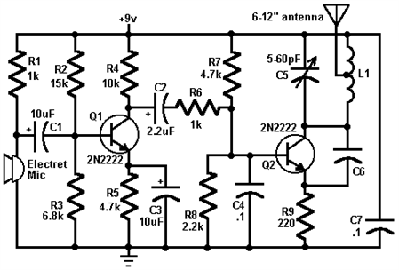
OK so i have a schematic for an FM jammer/transmitter - its both as it jamms the signal by transmitting nothing.

image

I want to change that nothing to a something (and i know for a fact that its posible with that schematic)So I need to hook up a 3.5mm jack somewhere on that schematic, my gues would be to connect it between the 0.01uF cap and GND , but am I correct? if not do you know where am i supposed to connect it to?

Again sorry that its not arduino related but any help is highly appreciated!

  • Sign in to reply
  • Cancel

Top Replies

  • Former Member
    Former Member over 13 years ago in reply to dirtdiver +1
    You are building an FM transmitter. You don't put an ear piece on the transmitter thats what the receiver is for.
Parents
  • Former Member
    0 Former Member over 13 years ago

    You will need a little more then that to add audio. Check this out.

    image

    • Cancel
    • Vote Up 0 Vote Down
    • Sign in to reply
    • Reject Answer
    • Cancel
  • dirtdiver
    0 dirtdiver over 13 years ago in reply to Former Member

    Crap.Ok first is the electret mic like a 3.5 mm jack? I mean can it be replaced with one?

    And this guy made it work with a  schematic using only one transistor and he claims that he used that exact schematic, he just cant remember where he wired the 3.5mm.Are you absolutely positive that it wont be so easy?

    • Cancel
    • Vote Up 0 Vote Down
    • Sign in to reply
    • Verify Answer
    • Cancel
  • R_Phoenix
    0 R_Phoenix over 13 years ago in reply to dirtdiver

    Wire up a jack, connect the ground, plug in a ear peice and test different points. The worst that can happen is you pop the ear peice.

    • Cancel
    • Vote Up 0 Vote Down
    • Sign in to reply
    • Verify Answer
    • Reject Answer
    • Cancel
  • Former Member
    0 Former Member over 13 years ago in reply to dirtdiver

    I take it you where going off this site.

    http://www.circuitstoday.com/fm-radio-jammer


    That is designed as a jammer only. All it has to do is flud the airways with noice to block out any other signal on the set frequency. Its only half the circuit needed if you actually want to transmit a decernable audio signal. The circuit needs to have 2 transistor in order to amplifiy the signal from teh microphone enough to get a good audio signal through to the receiver. The circuit your working with right now at best could transmit mourse code using key wired between ground and the negative lead of the capacitor. You can try putting a mic there but like i said you will have a hard time hearing it through a radio.

    • Cancel
    • Vote Up 0 Vote Down
    • Sign in to reply
    • Verify Answer
    • Cancel
  • dirtdiver
    0 dirtdiver over 13 years ago in reply to Former Member

    Ok, so i guess i will have to go with the schematic you provided, and again, can i replace the mic witha  3.5mm in that circuit?

    And what are the properties of L1 how many turns ?AWG  diameter?

    Thansk

    • Cancel
    • Vote Up 0 Vote Down
    • Sign in to reply
    • Verify Answer
    • Cancel
Reply
  • dirtdiver
    0 dirtdiver over 13 years ago in reply to Former Member

    Ok, so i guess i will have to go with the schematic you provided, and again, can i replace the mic witha  3.5mm in that circuit?

    And what are the properties of L1 how many turns ?AWG  diameter?

    Thansk

    • Cancel
    • Vote Up 0 Vote Down
    • Sign in to reply
    • Verify Answer
    • Cancel
Children
  • Former Member
    0 Former Member over 13 years ago in reply to dirtdiver

    Yes the mic can be replaced by a 3.5mm jack or any other audion jack/source you want to use. Use 6 to 8 turns of 22ga wire around a pencile for L1.

    • Cancel
    • Vote Up 0 Vote Down
    • Sign in to reply
    • Verify Answer
    • Reject Answer
    • Cancel
  • dirtdiver
    0 dirtdiver over 13 years ago in reply to Former Member

    Ok thatnks for the info!

    • Cancel
    • Vote Up 0 Vote Down
    • Sign in to reply
    • Verify Answer
    • Cancel
element14 Community

element14 is the first online community specifically for engineers. Connect with your peers and get expert answers to your questions.

  • Members
  • Learn
  • Technologies
  • Challenges & Projects
  • Products
  • Store
  • About Us
  • Feedback & Support
  • FAQs
  • Terms of Use
  • Privacy Policy
  • Legal and Copyright Notices
  • Sitemap
  • Cookies

An Avnet Company © 2025 Premier Farnell Limited. All Rights Reserved.

Premier Farnell Ltd, registered in England and Wales (no 00876412), registered office: Farnell House, Forge Lane, Leeds LS12 2NE.

ICP 备案号 10220084.

Follow element14

  • X
  • Facebook
  • linkedin
  • YouTube