element14 Community
element14 Community
    Register Log In
  • Site
  • Search
  • Log In Register
  • About Us
  • Community Hub
    Community Hub
    • What's New on element14
    • Feedback and Support
    • Benefits of Membership
    • Personal Blogs
    • Members Area
    • Achievement Levels
  • Learn
    Learn
    • Ask an Expert
    • eBooks
    • element14 presents
    • Learning Center
    • Tech Spotlight
    • STEM Academy
    • Webinars, Training and Events
    • Learning Groups
  • Technologies
    Technologies
    • 3D Printing
    • FPGA
    • Industrial Automation
    • Internet of Things
    • Power & Energy
    • Sensors
    • Technology Groups
  • Challenges & Projects
    Challenges & Projects
    • Design Challenges
    • element14 presents Projects
    • Project14
    • Arduino Projects
    • Raspberry Pi Projects
    • Project Groups
  • Products
    Products
    • Arduino
    • Avnet Boards Community
    • Dev Tools
    • Manufacturers
    • Multicomp Pro
    • Product Groups
    • Raspberry Pi
    • RoadTests & Reviews
  • Store
    Store
    • Visit Your Store
    • Choose another store...
      • Europe
      •  Austria (German)
      •  Belgium (Dutch, French)
      •  Bulgaria (Bulgarian)
      •  Czech Republic (Czech)
      •  Denmark (Danish)
      •  Estonia (Estonian)
      •  Finland (Finnish)
      •  France (French)
      •  Germany (German)
      •  Hungary (Hungarian)
      •  Ireland
      •  Israel
      •  Italy (Italian)
      •  Latvia (Latvian)
      •  
      •  Lithuania (Lithuanian)
      •  Netherlands (Dutch)
      •  Norway (Norwegian)
      •  Poland (Polish)
      •  Portugal (Portuguese)
      •  Romania (Romanian)
      •  Russia (Russian)
      •  Slovakia (Slovak)
      •  Slovenia (Slovenian)
      •  Spain (Spanish)
      •  Sweden (Swedish)
      •  Switzerland(German, French)
      •  Turkey (Turkish)
      •  United Kingdom
      • Asia Pacific
      •  Australia
      •  China
      •  Hong Kong
      •  India
      •  Korea (Korean)
      •  Malaysia
      •  New Zealand
      •  Philippines
      •  Singapore
      •  Taiwan
      •  Thailand (Thai)
      • Americas
      •  Brazil (Portuguese)
      •  Canada
      •  Mexico (Spanish)
      •  United States
      Can't find the country/region you're looking for? Visit our export site or find a local distributor.
  • Translate
  • Profile
  • Settings
Arduino
  • Products
  • More
Arduino
Arduino Forum Arduino resets when solenoid shuts off
  • Blog
  • Forum
  • Documents
  • Quiz
  • Events
  • Polls
  • Files
  • Members
  • Mentions
  • Sub-Groups
  • Tags
  • More
  • Cancel
  • New
Join Arduino to participate - click to join for free!
Actions
  • Share
  • More
  • Cancel
Forum Thread Details
  • State Suggested Answer
  • Replies 54 replies
  • Answers 16 answers
  • Subscribers 396 subscribers
  • Views 8630 views
  • Users 0 members are here
  • emi_protection
  • arduino
Related

Arduino resets when solenoid shuts off

Former Member
Former Member over 11 years ago

I have an arduino hooked to a 2 relay board. Each relay is opto-isolated. The arduino and board each have their own 5V power feed. The relays are switching 12V to controll a motor and a solenoid valve.

Sometimes when the solenoid turns off, the arduino resets. From what I've read, it's likely an EMI problem caused by the solenoid. If I disconnect the solenoid, I don't see the problem.

I've seen various suggestions about using a varistor or a diode, but I don't know which is better or what values to try. Any recommendations?

I'm assuming that the varistor or diode should be as close to the solenoid as possible, shorting the power and ground lines, is this correct?


Thanks,

Chris

  • Sign in to reply
  • Cancel

Top Replies

  • c4m4ch0
    c4m4ch0 over 8 years ago in reply to maranatha +3 suggested
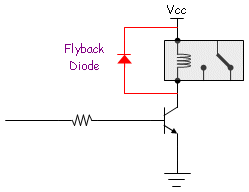
    Hello maranatha, you just need to connect the diode as it is in this image
  • Former Member
    Former Member over 11 years ago in reply to michaelkellett +2 suggested
    I put an IN4004 Rectifier Diode across the terminals of the solenoid and that seems to have solved the problem. I also found this page pretty educational: http://en.wikipedia.org/wiki/Flyback_diode
  • maranatha
    maranatha over 8 years ago in reply to Former Member +1
    Hi Chris Do you happen to have the connection diagram? I am facing similar problem and it would be really helpful if you could share a connection diagram (basically how you connect the rectifier diode…
Parents
  • mcb1
    0 mcb1 over 11 years ago

    it's likely an EMI problem caused by the solenoid

    I think you might be confused with back EMF which is where the energy in an inductive load (relay, solenoid or coil) causes a spike on the power supply, whenever it is turned  on or off.


    I suspect it is your 5v supply that is having the issue.

    You state there are seperate 'feeds' but this isn't the same as seperate supplies.


    Does it happen when you switch off the 12v supply, and run the sketch.?


    Sometimes it can be because the Arduino ground wire is also passing the 5v load ground.

    You should be connecting the Arduino ground to the power supply (wire #1)

    The relay board (if it has a ground) should have a ground to the power supply (wire #2)

    The ground on the 12v supply should also connect to the power supply (wire #3), although it isn't strictly necesary to connect it at all.


    While all three end up at the same point, the current flows are each contained in their own ground wire.


    It could be that your 5v supply doesn't have sufficent filtering for the surges created when inductive loads are switched.

    A large capacitor (4700 - 10,000 uF) across the 5v usually fixes the problem.


    Mark

    • Cancel
    • Vote Up 0 Vote Down
    • Sign in to reply
    • Verify Answer
    • Reject Answer
    • Cancel
  • michaelkellett
    0 michaelkellett over 11 years ago in reply to mcb1

    If you are switching  a solenoid with a relay you can easily have EMI problems that affect things some distance away (many metres or more).


    Put a diode across the solenoid coil (it must be arranged so that no current flows through the diode when the solenoid is energisesd ie annode to positive connection , cathode (usually marked with a ring or line on the diode body) to negative. You should always put dioded across relay or solenoid coils unless there is a good reason not to.


    When you turn the solenoid on the current takes time to build up - there are no surges, when you turn it off the voltage across the solenoid changes to try to keep the current going - (this is what inductors do) - because the relay is open ciruit the voltage spike across the inductor can be 100s or even 1000s of volts and the rise time can be very fast. It is this very rapidly changing high voltage which can couple into things and upset processors.  If you have a diode across the solenoid it gives the current  a path and the voltage won't get very high at all (but the solenoid will take longer to drop out). Relay contacts often make and break several times (bounce) and it may help to put a small capacitor across the coil. (0.1uf disc ceramic is often a good start).


    MK

    • Cancel
    • Vote Up 0 Vote Down
    • Sign in to reply
    • Verify Answer
    • Reject Answer
    • Cancel
  • Former Member
    0 Former Member over 11 years ago in reply to michaelkellett

    I put an IN4004 Rectifier Diode across the terminals of the solenoid and that seems to have solved the problem.

    I also found this page pretty educational: http://en.wikipedia.org/wiki/Flyback_diode

    • Cancel
    • Vote Up +2 Vote Down
    • Sign in to reply
    • Verify Answer
    • Reject Answer
    • Cancel
  • maranatha
    0 maranatha over 8 years ago in reply to Former Member

    Hi Chris


    Do you happen to have the connection diagram? I am facing similar problem and it would be really helpful if you could share a connection diagram (basically how you connect the rectifier diode).

    It is an old post, but I hope I will get some help image

    • Cancel
    • Vote Up +1 Vote Down
    • Sign in to reply
    • Verify Answer
    • Cancel
  • c4m4ch0
    0 c4m4ch0 over 8 years ago in reply to maranatha

    Hello maranatha, you just need to connect the diode as it is in this image

    flyback_diode.gif

    • Cancel
    • Vote Up +3 Vote Down
    • Sign in to reply
    • Verify Answer
    • Reject Answer
    • Cancel
  • maranatha
    0 maranatha over 8 years ago in reply to c4m4ch0

    Hello C4m4ch0


    Thanks for the diagram. Do the resistor and transistor are also required to solve the issue? If, yes, what kind of transistor and resistor value should I use?

    • Cancel
    • Vote Up 0 Vote Down
    • Sign in to reply
    • Verify Answer
    • Cancel
  • COMPACT
    0 COMPACT over 8 years ago in reply to maranatha

    Please post a picture of your set up.

    It'd be something quite simple to fix.

    • Cancel
    • Vote Up 0 Vote Down
    • Sign in to reply
    • Verify Answer
    • Cancel
Reply
  • COMPACT
    0 COMPACT over 8 years ago in reply to maranatha

    Please post a picture of your set up.

    It'd be something quite simple to fix.

    • Cancel
    • Vote Up 0 Vote Down
    • Sign in to reply
    • Verify Answer
    • Cancel
Children
  • COMPACT
    0 COMPACT over 8 years ago in reply to COMPACT

    Relays can't be driven directly from RPi's GPIO pins.


    A GPIO pin needs be connected to a current amplifier to drive a relay.

    The current amplifier can be as simple as a NPN transistor such as a BC548 or equivalent.

    (It's a transistor acting as a switch for the relay).


    It's called a current amplifier because a tiny bit of current coming out of the GPIO pin causes a larger current to energise the relay coil).


    The transistor base is driven through a 1k resistor to limit the current out of the GPIO pin.

    The diode across the relay is to create a discharge path for the relay coil to minimise the back EMF.

    Note that the polarity of the diode is backwards to the energising current flow.

    The diode could be an 1n914.


    When a relay coil is energised a magnetic field is created around it.

    When the power is disconnected the magnetic field collapses to create a current.

    This collapse can create a large voltage between the ends of the coil (seen in old radios as a spark gap) which we don't want in this application so a diode is used to complete the circuit to keep the voltage low.

    • Cancel
    • Vote Up +1 Vote Down
    • Sign in to reply
    • Verify Answer
    • Reject Answer
    • Cancel
  • COMPACT
    0 COMPACT over 8 years ago in reply to COMPACT

    You also need enough power budget on the driving voltage as not cause it to sag and stop correct operation.

    • Cancel
    • Vote Up 0 Vote Down
    • Sign in to reply
    • Verify Answer
    • Reject Answer
    • Cancel
  • maranatha
    0 maranatha over 8 years ago in reply to COMPACT

    The relay shield seems to have decoupling capacitors and the diode for combating the EMF effects.

    I was just wondering if the values of this components should be changed.

    • Cancel
    • Vote Up 0 Vote Down
    • Sign in to reply
    • Verify Answer
    • Cancel
  • COMPACT
    0 COMPACT over 8 years ago in reply to COMPACT

    Your picture and blurb explains a lot.

    The wiring and components seem right.


    What happens if you replace the PIR with a switch to emulate the PIR turning on and off?

    • Cancel
    • Vote Up 0 Vote Down
    • Sign in to reply
    • Verify Answer
    • Cancel
  • COMPACT
    0 COMPACT over 8 years ago in reply to COMPACT

    I'd replace the Rpi with just a resistor and a LED (or light bulb) until the problem is sorted.

    • Cancel
    • Vote Up 0 Vote Down
    • Sign in to reply
    • Verify Answer
    • Cancel
  • maranatha
    0 maranatha over 8 years ago in reply to COMPACT

    Hi


    I just replaced the PIR sensor with a push button. But it didn't solve the problem. It works when the HDMI display is connected but the relay unlatches when the HDMI display is unplagged from the RPi. Replacing the RPi with a LED will not help me in debugging, since the problem is in my opinion with the HDMI port.

    • Cancel
    • Vote Up 0 Vote Down
    • Sign in to reply
    • Verify Answer
    • Reject Answer
    • Cancel
  • COMPACT
    0 COMPACT over 8 years ago in reply to maranatha

    What happens with to Arduino behaviour if you power up the RPi directly from the battery pack without using the relay operating with and without the HDMI connection?

    • Cancel
    • Vote Up 0 Vote Down
    • Sign in to reply
    • Verify Answer
    • Reject Answer
    • Cancel
  • maranatha
    0 maranatha over 8 years ago in reply to COMPACT

    Hi

    That is good point. I just tried that now few times. The arduino behavior is quite normal. It doesn't reset.

    • Cancel
    • Vote Up 0 Vote Down
    • Sign in to reply
    • Verify Answer
    • Reject Answer
    • Cancel
  • COMPACT
    0 COMPACT over 8 years ago in reply to maranatha

    What happens when you have the Rpi:


    a. in close proximity to the Arduino

    b. with just one of the power leads connected to the relay (try each one separately)

    • Cancel
    • Vote Up 0 Vote Down
    • Sign in to reply
    • Verify Answer
    • Cancel
  • maranatha
    0 maranatha over 8 years ago in reply to COMPACT

    Hi COMPACT


    I am not sure if I understood clearly point b). Does it mean the other lead is just on the air?

    • Cancel
    • Vote Up 0 Vote Down
    • Sign in to reply
    • Verify Answer
    • Cancel
element14 Community

element14 is the first online community specifically for engineers. Connect with your peers and get expert answers to your questions.

  • Members
  • Learn
  • Technologies
  • Challenges & Projects
  • Products
  • Store
  • About Us
  • Feedback & Support
  • FAQs
  • Terms of Use
  • Privacy Policy
  • Legal and Copyright Notices
  • Sitemap
  • Cookies

An Avnet Company © 2025 Premier Farnell Limited. All Rights Reserved.

Premier Farnell Ltd, registered in England and Wales (no 00876412), registered office: Farnell House, Forge Lane, Leeds LS12 2NE.

ICP 备案号 10220084.

Follow element14

  • X
  • Facebook
  • linkedin
  • YouTube