element14 Community
element14 Community
    Register Log In
  • Site
  • Search
  • Log In Register
  • About Us
  • Community Hub
    Community Hub
    • What's New on element14
    • Feedback and Support
    • Benefits of Membership
    • Personal Blogs
    • Members Area
    • Achievement Levels
  • Learn
    Learn
    • Ask an Expert
    • eBooks
    • element14 presents
    • Learning Center
    • Tech Spotlight
    • STEM Academy
    • Webinars, Training and Events
    • Learning Groups
  • Technologies
    Technologies
    • 3D Printing
    • FPGA
    • Industrial Automation
    • Internet of Things
    • Power & Energy
    • Sensors
    • Technology Groups
  • Challenges & Projects
    Challenges & Projects
    • Design Challenges
    • element14 presents Projects
    • Project14
    • Arduino Projects
    • Raspberry Pi Projects
    • Project Groups
  • Products
    Products
    • Arduino
    • Avnet Boards Community
    • Dev Tools
    • Manufacturers
    • Multicomp Pro
    • Product Groups
    • Raspberry Pi
    • RoadTests & Reviews
  • Store
    Store
    • Visit Your Store
    • Choose another store...
      • Europe
      •  Austria (German)
      •  Belgium (Dutch, French)
      •  Bulgaria (Bulgarian)
      •  Czech Republic (Czech)
      •  Denmark (Danish)
      •  Estonia (Estonian)
      •  Finland (Finnish)
      •  France (French)
      •  Germany (German)
      •  Hungary (Hungarian)
      •  Ireland
      •  Israel
      •  Italy (Italian)
      •  Latvia (Latvian)
      •  
      •  Lithuania (Lithuanian)
      •  Netherlands (Dutch)
      •  Norway (Norwegian)
      •  Poland (Polish)
      •  Portugal (Portuguese)
      •  Romania (Romanian)
      •  Russia (Russian)
      •  Slovakia (Slovak)
      •  Slovenia (Slovenian)
      •  Spain (Spanish)
      •  Sweden (Swedish)
      •  Switzerland(German, French)
      •  Turkey (Turkish)
      •  United Kingdom
      • Asia Pacific
      •  Australia
      •  China
      •  Hong Kong
      •  India
      •  Korea (Korean)
      •  Malaysia
      •  New Zealand
      •  Philippines
      •  Singapore
      •  Taiwan
      •  Thailand (Thai)
      • Americas
      •  Brazil (Portuguese)
      •  Canada
      •  Mexico (Spanish)
      •  United States
      Can't find the country/region you're looking for? Visit our export site or find a local distributor.
  • Translate
  • Profile
  • Settings
Arduino
  • Products
  • More
Arduino
Arduino Forum limit switches within a counter
  • Blog
  • Forum
  • Documents
  • Quiz
  • Events
  • Polls
  • Files
  • Members
  • Mentions
  • Sub-Groups
  • Tags
  • More
  • Cancel
  • New
Join Arduino to participate - click to join for free!
Actions
  • Share
  • More
  • Cancel
Forum Thread Details
  • State Verified Answer
  • Replies 10 replies
  • Answers 2 answers
  • Subscribers 392 subscribers
  • Views 2284 views
  • Users 0 members are here
Related

limit switches within a counter

Former Member
Former Member over 11 years ago

Hi folks,

Im a technology teacher in Scotland and the powers above have decided that we move from our old PBASIC run Stamp boards, and use Arduino. It has also been decided this will start of next month! this means during my holidays I have been left with no choice but to learn the language and how it works myself, but to create a scheme of work for my pupils to follow. Most of what Ive done is based on Jeremy Blums brilliant online tutorials , and things that are different I was mostly able to work out by looking up.


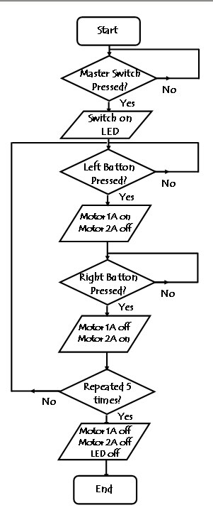
I have came across a problem though and for the life of my I cant seem to solve it and I was hoping someone on here could help! Ive designed a project of dancing ballerina toy (my feeble attempts to try and get more girls into Engineering). When a master switch is pressed, it will put on an ultabrite LED to act as a spotlight for the dancer. The ballerina will then "dance" by sitting on top of a turntable that will rotate one way until it hits a limit switch. When it hits this limit switch it will rotate the other direction until it hits another limit switch, sending it back the original direction. This dancing will repeat 5 times, then everything will switch off.


This is a flowchart of what I'm attempting to do, which will hopefully make things a little clearer:


image


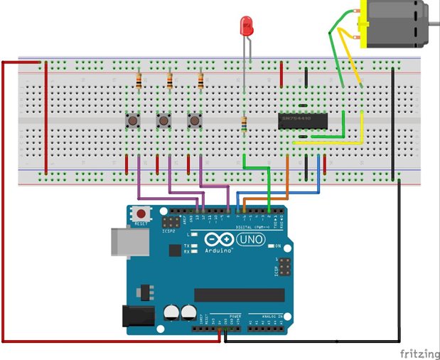
This is how I have wired up my Arduino Uno:


image


and this is my attempt at the code. It was originally more complicated added in debouncing and commands to keep outputs on once the switches have been presssed, but I deleted all that to try and work out what is going wrong.


/*

dancing toy System

*/


int MasterSwitchPin = 13;      // Master switch

int LeftSwitchPin = 12;        // Makes motor turn left

int RightSwitchPin = 8;        // Makes motor turn right

int Motor1APin = 7;            // H-bridge leg 1

int Motor2APin = 6;            // H-bridge leg 2

int LEDPin = 2;                // LED


void setup()

{

  Serial.begin(9600);

  pinMode (MasterSwitchPin, INPUT);

  pinMode (LeftSwitchPin, INPUT);

  pinMode (RightSwitchPin, INPUT);

  pinMode (Motor1APin, OUTPUT);

  pinMode (Motor2APin, OUTPUT);

  pinMode (LEDPin, OUTPUT);

}


void loop()

{

   if (digitalRead(MasterSwitchPin) == HIGH)

     {

       digitalWrite(LEDPin, HIGH);

     }

     Serial.print("button pressed LED on");

for (int counter = 1 ; counter <= 5; counter = counter +1) 

   { 

    while (digitalRead(LeftSwitchPin) == HIGH)

      {

      digitalWrite(Motor1APin, HIGH);

      digitalWrite(Motor2APin, LOW);

      Serial.print("motor goes one way");

      }      

      delay(1000);


    while (digitalRead(RightSwitchPin) == HIGH)

      {

      digitalWrite(Motor1APin, LOW);

      digitalWrite(Motor2APin, HIGH);

      Serial.print("motor goes the other wat way");

      }

  delay(1000);     

   }

   Serial.print("repeated 5 times");

       digitalWrite(LEDPin, LOW);

       digitalWrite(Motor1APin, LOW);

       digitalWrite(Motor2APin, LOW);

       Serial.print("switch everything off");

}


can anyone help me please and fix my code? thanks in advance!!!

  • Sign in to reply
  • Cancel
Parents
  • shabaz
    0 shabaz over 11 years ago

    Hi Paul,


    Hopefully someone may respond sooner with better info (busy day for me today unfortunately for the next few hours, so this is a quick reply), but I had a few questions/suggestions:

    1. What is the current symptom? Does any of it function, e.g. does LED turn on, does it stay on, etc. Does button detection work? Does the motor appear to get energised slightly?

    2. Could you try powering the SNxxx chip from a separate supply, not from the Arduino board supply? To see what happens?

    3. Could you place a 100uF capacitor across the supply rails close to the SNxxxx chip, and also a 100nF capacitor across the supply rails close to the chip too?

    • Cancel
    • Vote Up 0 Vote Down
    • Sign in to reply
    • Verify Answer
    • Reject Answer
    • Cancel
  • Former Member
    0 Former Member over 11 years ago in reply to shabaz

    Hi Shabaz, thanks for getting back to me.


    Firstly the LED goes on without the master button being pressed (currently playing about with that thinking it might be a pull up/pull down resistor issue).


    from there my left/right limit buttons but its only working say 20%(which makes me think its more than just a button bouncing). then Even It doesnt seem to be responding that well to the button presses though - one works better than the other, but instead of this one button making it go say clockwise, it will do that, then change direction of motor a few times.


    Even when i do get it to follow the left, then right commands it doesnt stop after my 5 loops. Infact the serial monitor is saying the 5 loops are completed before any buttons are even pressed which makes me thing ive set up the decisions from the flowchart wrong (im not sure which command to use instead as cant find anything online.)


    Im now attempting to modify my original and more complex program by adding in the booleans and debouncing again    


    here is my code:


    /*

    dancing toy System

    */


    int MasterSwitchPin = 13;      // Master switch

    int LeftSwitchPin = 12;        // Makes motor turn left

    int RightSwitchPin = 8;        // Makes motor turn right

    int Motor1APin = 7;            // H-bridge leg 1

    int Motor2APin = 6;            // H-bridge leg 2

    int LEDPin = 2;                // LED


    boolean MasterlastButton = LOW;                

    boolean MastercurrentButton = LOW;     

    boolean MasterLEDon = false;


    boolean LeftlastButton = LOW;                

    boolean LeftcurrentButton = LOW;     

    boolean Leftmotoron = false;


    boolean RightlastButton = LOW;                

    boolean RightcurrentButton = LOW;     

    boolean Rightmotoron = false;


    void setup()

    {

      Serial.begin(9600);

      pinMode (MasterSwitchPin, INPUT);

      pinMode (LeftSwitchPin, INPUT);

      pinMode (RightSwitchPin, INPUT);

      pinMode (Motor1APin, OUTPUT);

      pinMode (Motor2APin, OUTPUT);

      pinMode (LEDPin, OUTPUT);

    }


    boolean Masterdebounce(boolean last)           

    {

            boolean current = digitalRead(MasterSwitchPin);

             if (last != current)                   

    {

    delay(5);             

    current = digitalRead(MasterSwitchPin);     

    }

    return current;       

    }


    boolean Leftdebounce(boolean last)           

    {

            boolean current = digitalRead(LeftSwitchPin);

             if (last != current)                   

    {

    delay(5);             

    current = digitalRead(LeftSwitchPin);     

    }

    return current;       

    }


    boolean Rightdebounce(boolean last)           

    {

            boolean current = digitalRead(RightSwitchPin);

             if (last != current)                   

    {

    delay(5);             

    current = digitalRead(RightSwitchPin);     

    }

    return current;       

    }


    void loop()

    {

      MastercurrentButton = Masterdebounce(MasterlastButton);

      LeftcurrentButton = Leftdebounce(LeftlastButton);

      RightcurrentButton = Rightdebounce(RightlastButton);


       Serial.print("starting");

       if (digitalRead(MasterSwitchPin) == HIGH && MasterlastButton == LOW)

         {

           MasterLEDon = !MasterLEDon;

           digitalWrite(LEDPin, HIGH);

           Serial.print("button pressed LED on");


    for (int counter = 1 ; counter <= 5; counter = counter +1) 

       { 

        while (digitalRead(LeftSwitchPin) == HIGH && LeftlastButton == LOW)

          {

            Leftmotoron = !Leftmotoron;

            Rightmotoron = !Rightmotoron;


          digitalWrite(Motor1APin, HIGH);

          digitalWrite(Motor2APin, LOW);

          Serial.print("motor goes one way");

          }      

          delay(1000);


        while (digitalRead(RightSwitchPin) == HIGH && RightlastButton == LOW)

          {

            Leftmotoron = !Leftmotoron;

            Rightmotoron = !Rightmotoron;


          digitalWrite(Motor1APin, LOW);

          digitalWrite(Motor2APin, HIGH);

          Serial.print("motor goes the other wat way");

          }

      delay(1000);     

       }

       Serial.print("repeated 5 times");

           digitalWrite(LEDPin, LOW);

           digitalWrite(Motor1APin, LOW);

           digitalWrite(Motor2APin, LOW);

           Serial.print("switch everything off");

    }

    }


    all this does though is switch my LED off when the master button is pressed (LED goes on as soon as sketch is uploaded) and none of the motor controls work.

    • Cancel
    • Vote Up 0 Vote Down
    • Sign in to reply
    • Verify Answer
    • Cancel
  • shabaz
    0 shabaz over 11 years ago in reply to Former Member

    Hi Paul,


    I don't think any debouncing is needed, so the first code is more usable I think. I modified it slightly (created #define to clean it up, and rearranged the location of code so the loops are a bit cleaner):


    /*
    dancing toy System
    */
    
    int MasterSwitchPin = 13;      // Master switch
    int LeftSwitchPin = 12;        // Makes motor turn left
    int RightSwitchPin = 8;        // Makes motor turn right
    int Motor1APin = 7;            // H-bridge leg 1
    int Motor2APin = 6;            // H-bridge leg 2
    int LEDPin = 2;                // LED
    
    
    #define LED_ON digitalWrite(LEDPin, LOW)
    #define LED_OFF digitalWrite(LEDPin, HIGH)
    
    
    #define MOTOR_LEFT digitalWrite(Motor2APin, LOW);digitalWrite(Motor1APin, HIGH)
    #define MOTOR_RIGHT digitalWrite(Motor1APin, LOW);digitalWrite(Motor2APin, HIGH)
    #define MOTOR_STOP digitalWrite(Motor1APin, LOW);digitalWrite(Motor2APin, LOW)
    
    
    #define BUTTON_PRESSED (digitalRead(MasterSwitchPin) == HIGH)
    #define END1_HIT (digitalRead(LeftSwitchPin) == HIGH)
    #define END2_HIT (digitalRead(RightSwitchPin) == HIGH)
    
    void setup()
    {
      Serial.begin(9600);
      pinMode (MasterSwitchPin, INPUT);
      pinMode (LeftSwitchPin, INPUT);
      pinMode (RightSwitchPin, INPUT);
      pinMode (Motor1APin, OUTPUT);
      pinMode (Motor2APin, OUTPUT);
      pinMode (LEDPin, OUTPUT);
    }
    
    void loop()
    {
      LED_OFF;
      while(!BUTTON_PRESSED); // wait here until the button is pressed
      LED_ON;
      Serial.print("button pressed LED on");
      for (int counter = 1 ; counter <= 5; counter = counter +1)
      {
        MOTOR_LEFT;
        Serial.print("motor goes one way");
        while (!END1_HIT)
        {
        // do nothing, just delay a very tiny amount
        delay(10);
        }
       MOTOR_STOP;   
        delay(1000);
      
        MOTOR_RIGHT;
        Serial.print("motor goes the other way");
        while (!END2_HIT)
        {
          // do nothing, just delay a very tiny amount
        delay(10);
        }
        MOTOR_STOP;
        delay(1000);   
      } // end of for loop
    
      Serial.print("repeated 5 times");
    }


    I have no idea if the code will work (I don't have an Arduino) but I suspect it is closer to what is needed. Could you give it a test, or at least test a modified version of this, so that you can confirm the #define lines do what is expected, and then the program logic can be ironed out.


    The exclamation marks indicate boolean NOT by the way.

    Also, I'm not sure the circuit is correct. I think pin 1 of that integrated circuit needs to go somewhere - can you connect it to the positive supply?


    Also, the LED is connected with one end to +ve according to your diagram, so by default the LED would be lit if the output is LOW. I've taken that into account in the code, so that the #define LED_ON writes LOW to the pin, and LED_OFF writes HIGH to the pin.


    Also, it is fairly mandatory to have a large-ish capacitor (maybe 100uF) and a 100nF capacitor across the supply rails very close to the motor control IC, i.e. directly near pin 4 and pin 8.

    Finally, your motor controller may be causing effects to the supply rail, causing unexpected behaviour from the Arduino. To eliminate that during testing, you need a separate supply for the motor controller (i.e. disconnect pins 8 and 16 of the IC, and feed a separate battery +ve supply to those pins, and connect the battery -ve to the ground.


    EDIT: corrected a few things in the code and text.

    • Cancel
    • Vote Up 0 Vote Down
    • Sign in to reply
    • Reject Answer
    • Cancel
  • Robert Peter Oakes
    0 Robert Peter Oakes over 11 years ago in reply to shabaz

    I like what you did with this


    Just a slight improvement can be done by extending your approach to defines, it wont make a huge difference in this code but as a practice it is a good habit to get into


    #define MasterSwitchPin   13       // Master switch 
    #define LeftSwitchPin   12         // Makes motor turn left 
    #define RightSwitchPin   8         // Makes motor turn right 
    #define Motor1APin   7             // H-bridge leg 1 
    #define Motor2APin   6             // H-bridge leg 2 
    #define LEDPin   2                 // LED

    this way it saves more memory and eliminates type and additional code to copy from the INT variable at tun time

    • Cancel
    • Vote Up 0 Vote Down
    • Sign in to reply
    • Verify Answer
    • Cancel
Reply
  • Robert Peter Oakes
    0 Robert Peter Oakes over 11 years ago in reply to shabaz

    I like what you did with this


    Just a slight improvement can be done by extending your approach to defines, it wont make a huge difference in this code but as a practice it is a good habit to get into


    #define MasterSwitchPin   13       // Master switch 
    #define LeftSwitchPin   12         // Makes motor turn left 
    #define RightSwitchPin   8         // Makes motor turn right 
    #define Motor1APin   7             // H-bridge leg 1 
    #define Motor2APin   6             // H-bridge leg 2 
    #define LEDPin   2                 // LED

    this way it saves more memory and eliminates type and additional code to copy from the INT variable at tun time

    • Cancel
    • Vote Up 0 Vote Down
    • Sign in to reply
    • Verify Answer
    • Cancel
Children
  • shabaz
    0 shabaz over 11 years ago in reply to Robert Peter Oakes

    Hi Peter,


    You're right, much better practice to rip out those 'int's in the code too into #defines.

    Basically something like

    #define MASTER_SWITCH_PIN 13

    etc..

    (the '=' and '// xyz comment' need to be removed) - I also like capitalizing all #defines, just so they are clear they are not variables.

    • Cancel
    • Vote Up 0 Vote Down
    • Sign in to reply
    • Verify Answer
    • Cancel
  • Robert Peter Oakes
    0 Robert Peter Oakes over 11 years ago in reply to shabaz

    the "=" are gone, you must have read it the moment I posted and did not see the almost immediate correction image


    the comments are actually legal there and should not be discouraged, though appropriate names of the defines should make it clear what they do and as they take no final memory space should not need to be abbreviated so if the names are obvious then you could choose to drop the comments. Unless you need to express perhaps reasonable limits for the value of the define or something


    I agree with the capitalization of the defines in order to easily identify them from variables


    Peter

    • Cancel
    • Vote Up 0 Vote Down
    • Sign in to reply
    • Verify Answer
    • Cancel
element14 Community

element14 is the first online community specifically for engineers. Connect with your peers and get expert answers to your questions.

  • Members
  • Learn
  • Technologies
  • Challenges & Projects
  • Products
  • Store
  • About Us
  • Feedback & Support
  • FAQs
  • Terms of Use
  • Privacy Policy
  • Legal and Copyright Notices
  • Sitemap
  • Cookies

An Avnet Company © 2025 Premier Farnell Limited. All Rights Reserved.

Premier Farnell Ltd, registered in England and Wales (no 00876412), registered office: Farnell House, Forge Lane, Leeds LS12 2NE.

ICP 备案号 10220084.

Follow element14

  • X
  • Facebook
  • linkedin
  • YouTube